CT-Turns-Ratio Modification
advertisement

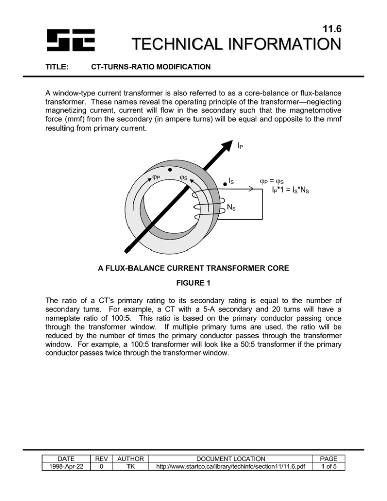
11.6 TECHNICAL INFORMATION TITLE: CT-TURNS-RATIO MODIFICATION A window-type current transformer is also referred to as a core-balance or flux-balance transformer. These names reveal the operating principle of the transformer—neglecting magnetizing current, current will flow in the secondary such that the magnetomotive force (mmf) from the secondary (in ampere turns) will be equal and opposite to the mmf resulting from primary current. IP ϕP ϕS IS ϕP = ϕS IP*1 = IS*NS NS A FLUX-BALANCE CURRENT TRANSFORMER CORE FIGURE 1 The ratio of a CT’s primary rating to its secondary rating is equal to the number of secondary turns. For example, a CT with a 5-A secondary and 20 turns will have a nameplate ratio of 100:5. This ratio is based on the primary conductor passing once through the transformer window. If multiple primary turns are used, the ratio will be reduced by the number of times the primary conductor passes through the transformer window. For example, a 100:5 transformer will look like a 50:5 transformer if the primary conductor passes twice through the transformer window. DATE 1998-Apr-22 REV 0 AUTHOR TK DOCUMENT LOCATION http://www.startco.ca/library/techinfo/section11/11.6.pdf PAGE 1 of 5 11.6 TECHNICAL INFORMATION TITLE: CT-TURNS-RATIO MODIFICATION Adding or subtracting secondary turns can also change the ratio of a current transformer. A current transformer will have the line side of its primary marked H1 and the end of its secondary winding with the same polarity marked X1 (see Figure 2), or it will have H1 and X1 indicated with dots. LOAD BURDEN X1 LOAD SIDE X2 PRIMARY CONDUCTOR H1 LINE SIDE CURRENT TRANSFORMER FIGURE 2 DATE 1998-Apr-22 REV 0 AUTHOR TK DOCUMENT LOCATION http://www.startco.ca/library/techinfo/section11/11.6.pdf PAGE 2 of 5 11.6 TECHNICAL INFORMATION TITLE: CT-TURNS-RATIO MODIFICATION To increase the CT ratio, the number of secondary turns must be increased. To add turns to the secondary winding, pass the X1 secondary lead through the transformer window from H2 to H1, as shown in Figure 3 SECONDARY LEADS LOAD SIDE X1 X2 H1 LINE SIDE ADDING SECONDARY TURNS FIGURE 3 DATE 1998-Apr-22 REV 0 AUTHOR TK DOCUMENT LOCATION http://www.startco.ca/library/techinfo/section11/11.6.pdf PAGE 3 of 5 11.6 TECHNICAL INFORMATION TITLE: CT-TURNS-RATIO MODIFICATION To decrease the CT ratio, the number of secondary turns must be decreased. To subtract external turns from the CT secondary winding, pass the X1 secondary lead through the transformer window from H1 to H2, as shown in Figure 4. SECONDARY LEADS LOAD SIDE X1 X2 H1 LINE SIDE SUBTRACTING SECONDARY TURNS FIGURE 4 Example 1: To increase a 25-5 A CT to a ratio of 100-5 A, 15 turns must be added to the CT secondary - a 25-5 A CT has a turns ratio of 5:1, and a 100-5 A CT has a turns ratio of 20:1. Pass the X1 secondary lead is through the transformer window 15 times from H2 to H1. CT RATIO 25-5 A 50-5 A 75-5 A 100-5 A DATE 1998-Apr-22 REV 0 TURNS ADDED TO 25-5 A CT SECONDARY 0 turns 5 turns 10 turns 15 turns AUTHOR TK TURNS RATIO 5:1 10:1 15:1 20:1 DOCUMENT LOCATION http://www.startco.ca/library/techinfo/section11/11.6.pdf PAGE 4 of 5 11.6 TECHNICAL INFORMATION TITLE: CT-TURNS-RATIO MODIFICATION Example 2: To decrease a 500-5 A CT to a ratio of 425-5 A, 15 turns must be subtracted from the CT secondary - a 500-5 A CT has a turns ratio of 100:1, and a 425-5 A CT has a turns ratio of 85:1. Pass the X1 secondary lead is through the transformer window 15 times from H1 to H2. CT RATIO 500-5 A 475-5 A 450-5 A 425-5 A TURNS SUBTRACTED FROM 500-5 A CT SECONDARY 0 turns 5 turns 10 turns 15 turns TURNS RATIO 100:1 95:1 90:1 85:1 NOTE 1: There will be an extra burden on the CT from the additional lead length required to wrap the CT. NOTE 2: Changing the CT turns ratio is not a desirable method for sizing CT’s. It is better to properly size the CT ratio to the specific application. When the CT ratio is changed using this method, the CT manufacturer’s data will no longer apply to the CT. DATE 1998-Apr-22 REV 0 AUTHOR TK DOCUMENT LOCATION http://www.startco.ca/library/techinfo/section11/11.6.pdf PAGE 5 of 5


