SchemaTIc SymBOlS
advertisement

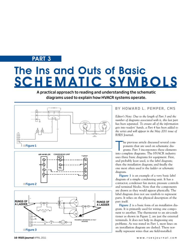
Part 3 The Ins and Outs of Basic Sch e matic Symbol s A practical approach to reading and understanding the schematic diagrams used to explain how HVACR systems operate. By H owa r d L . P e m p e r , C MS Editor’s Note: Due to the length of Part 3 and the number of diagrams associated with it, this last part has been separated. To ensure all of the information gets into readers’ hands, a Part 4 has been added to the series and will appear in the May 2011 issue of RSES Journal. T Figure 1 Figure 2 Figure 3 10 RSES Journal APRIL 2011 RUNGS OF A LADDER RUNGS OF A LADDER he previous article discussed several components that are used on schematic diagrams. Part 3 incorporates these elements into complete diagrams. The HVACR industry uses three basic diagrams for equipment. First, and probably least used, is the label diagram; then the installation diagram; and finally the one most often used is the ladder or schematic diagram. Figure 1 is an example of a very basic label diagram of a simple condensing unit. It has a contactor, condenser fan motor, pressure controls and terminal blocks. Note that the components are drawn as they would appear physically. The label diagram does not use symbols to represent parts. It relies on the physical description of the part itself. Figure 2 is a basic form of an installation diagram. It is primarily used for wiring one component to another. The thermostat to an air-conditioner as shown in Figure 2, are just the external terminals. It does not help in diagnosing any problems. As was stated in Part 1, most lines on an installation diagram are dashed. These normally represent wires that are field-installed. w w w. r s e s j o u r n a l . co m "c" Figure 5a "a" "e" Figure 5b "d" "b" ed to an external thermostat that is not shown. These are in the low-voltage circuit. The compressor is protected by the low-pressure switch LPS1 and the high-pressure switch HPS1. Note that the safety switches are wired in a series configuration. Figure 4 CAP CC CCHR CFM COMP DISC FPS FU GND GV CAPACITOR COMPRESSOR CONTACTOR CRANKCASE HEATER CONDENSER FAN MOTOR COMPRESSOR DISCONNECT FREEZE PROTECTION SWITCH FUSE GROUND GAS VALVE Figure 6 IFM IFMR IGNC IGNCR HPS LPS LS RS TB TRAN INDOOR FAN MOTOR INDOOR FAN MOTOR RELAY IGNITION CONTROL IGNITION CONTROL RELAY HIGH PRESSURE SWITCH LOW PRESSURE SWITCH LIMIT SWITCH ROLLOUT SWITCH TERMINAL BOARD TRANSFORMER Figure 4 Legend Figure 3 is the ladder diagram of Figure 1. The reason it is called a ladder diagram is because the components are normally drawn in a horizontal plane while the power supply wires are vertical. Together, they look like rungs on a step ladder. These diagrams simplify the circuits, which will aid in diagnosing any electrical problem with the unit. The contactor coil C-1 controls the two sets of contacts marked C-1 terminals 11, 21, 12 and 22. These are at line-voltage potential. The contactor coil C-1 is controlled by the terminals C and Y1 on the terminal block TB-2. These are connectw w w. r s e s j o u r n a l . co m Complex diagrams in basics At first glance, most schematics look complex, but isolating or breaking them down into separate areas helps make troubleshooting easier. Figure 4 represents a generic package rooftop gas/electric unit and is more complex, but can be broken down into four or five basic parts. The two most important divisions of a schematic that most manufacturers do not deviate from is the letter “a” at the top of Figure 4, normally considered the high-voltage section; and the letter “b,” usually the low-voltage section. The normal breaking point between the low and high voltage of any schematic is a transformer, which is represented by the letter “e.” Remember there can be more than one transformer on a schematic, depending upon the equipment. The letter “c” is considered the line side of the diagram, which is normally where the controls and switches are drawn; and the letter “d” represents the load side where the power-consuming components are located. Several components on the diagram only have a letter next to them; each of which can be deciphered using an accompanying legend. APRIL 2011 RSES Journal 11 Figure 7 Figure 13 Figure 8 Figure 9 Figure 10 Figure 11 Figure 12 Now, to put all of these components together: The series of numbers listed vertically from the top of most diagrams to the bottom represents line-side numbering. In Figure 5a, line 1 is the disconnect switch; and in Figure 5b, line 22 is the capacitor for the condenser-fan motor (CFM). Manufacturers will frequently use these line numbers when describing the sequence of operations. The numbers grouped together at specific points or at specific loads on the right side of a diagram represent load-side numbering. In Figure 6, the numbers 10, 13, 17 and 21 depict the safety controls and the compressor contactor (CC). Each of these numbers represents a line that corresponds to a 12 RSES Journal APRIL 2011 Figure 14 switch or control that the coil operates. Figure 7 shows the CC is controlling N/O contacts CC1 and CC2 to start the compressor; and CC4 at line 21 which is a N/O set of open contacts. This in turn energizes on the CFM, as is illustrated in Figure 8. Lastly, the compressor contactor CC also is controlling CC3 at line 17. Note that the number is underlined. Any time an underlined number on the load side of a schematic appears, it will indicate an N/C set of contacts. This switch will open when the compressor is energized, de-energizing the crankcase heater (CCHR) shown in Figure 9. The next controlling relay shown in Figure 10 is the indoor-fan-motor relay (IFMR), which is used to control the indoor-fan-motor’s speed from heating (low speed) to cooling (high speed). This device controls a single-pole double-throw (SPDT) set of contacts at lines 28 and 30. Note in Figure 4 line 28 by the IFMR is underlined, so is N/C and will switch over when the coil energized. The last controlling device is the ignition control (IGNC), which closes the gas valve (IGNCR2) at line 51, as illustrated in Figure 11. The IFM is turned on after a certain period of time and turns on the fan at line 28. This is determined by the IGNCR1, shown in Figure 12. Note that w w w. r s e s j o u r n a l . co m indoor outdoor Figure 15 Figure 16 Figure 17 w w w. r s e s j o u r n a l . co m the controlling coil can be at a different position on the diagram than the contacts, as illustrated in the previous diagrams. The last item to connect to this unit to make it run would be a thermostat. Figure 13 is an illustration of a generic thermostat connected to TB-1. To facilitate the location of components used on schematics, some manufacturers will place a component layout diagram next to the wiring diagram. This speeds up finding a failed element or component of the circuit. Figure 14 is an example of a component diagram and a legend. Figure 15 is diagram of hypothetical generic heat-pump system. It is a combination of a ladder, installation and component diagram. Starting with the circuit on the right side at the top, we find that the compressor has a three-phase power supply. It has a crankcase heater that is controlled by the contactor’s open contacts. Figure 16 illustrates that when the contacts are open, current flows through the crankcase heater (which per this legend is now referenced as CCHTR) and the compressor’s windings, maintaining enough temperature in the compressor to keep the oil and refrigerant separate. When the contactor’s contacts close the CCHTR is de-activated. APRIL 2011 RSES Journal 13 Figure 18 Figure 19 a b O C d DFT c e . R . R f C Editors Note: These points are from Figure 18 and 19. 14 RSES Journal APRIL 2011 Figure 17 illustrates the single-phase outdoor-fan motor (OFM). Note that the motor is energized when power is applied to the compressor. However, this is a heat-pump system, and the fan motor must be off when in defrost. This is accomplished with the N/C defrost relay (DR) contacts. The last item on the outdoor section of this heat pump is the printed circuit board PCB123456. This control’s defrost, reversing valve and the compressor are shown in Figure 18. There are a few items of note about the PCB. The first is some of the hardwired connections that are made to push on connectors right on the board, such as the reversing-valve solenoid (RVS). It is made to terminals O(a) and C(b). The DFT (defrost thermostat) is connected to the PCB at points R(c)and DFT(d). There are a number of devices that cannot be removed from the board and can be somewhat difficult to troubleshoot. Deciding which circuit controls each component can be figured out by inspecting the diagram of the PCB. The next series of hard-wired devices are the safety controls and the contactor, which are shown in Figure 19. The high-pressure switch is wired directly to the contactor and the low-pressure switch is wired to the PCB at R(e). The other side of the contactor is wired to the PCB at C(f). The indoor section of Figure 15 is shown more clearly in Figure 20, where several different circuits not yet discussed are incorporated in this portion of the system. w w w. r s e s j o u r n a l . co m Figure 21 illustrates the operation of the first sequencer (SEQ-1), which has a two-fold function. The first is when W2 is energized and the SEQ-1 starts its timing process. Upon completion of the timing the contacts SEQ-1 close. This causes the HTR-1 is energized. Simultaneously, the fan motor (FM) is energized in medium speed. If more heat is required, the next two sequencers, SEQ-2 and SEQ-3, will be energized causing the heaters HTR-2 and HTR-3 to become energized, as is shown in Figure 22. Next month, Part 4 will break down the more complex schematic of a ficticious two-stage heating/cooling rooftop unit. Howard L. Pemper, CMS, is the Supervisor of Training and Technical Support for Malden, MA-based Distributor Corp. He is a former RSES E&E Board Member and Editor of the Electrical Training Manuals. He can be reached at hlpemper@rcn.com. Figure 20 Figure 21 Figure 22 w w w. r s e s j o u r n a l . co m APRIL 2011 RSES Journal 15
