Ideal OP AMP Model V
advertisement
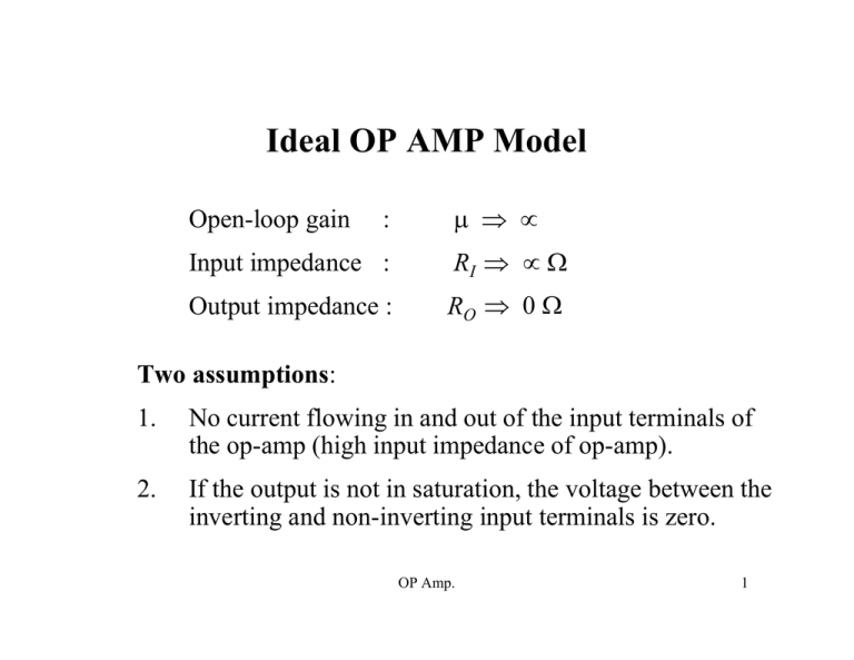
Ideal OP AMP Model Open-loop gain : µ ⇒ ∝ Input impedance : RI ⇒ ∝ Ω Output impedance : RO ⇒ 0 Ω Two assumptions: 1. No current flowing in and out of the input terminals of the op-amp (high input impedance of op-amp). 2. If the output is not in saturation, the voltage between the inverting and non-inverting input terminals is zero. OP Amp. 1 Ideal OP AMP Model V+ V− i+ = 0 +V i− = 0 Vout −V V+ = V− and i+ = i− = 0 The current in or out of either input is negligible. If the output is not in saturation, the voltage between the two input terminals is zero. OP Amp. 2 Non-inverting Amplifier +V i+ V+ Vout V− −V VS R1 i− R2 V− = OP Amp. R2 R1+ R2 V out 3 Non-inverting Amplifier The voltage at the inverting input, V− can be determined by voltage division: V− = R2 R1+ R2 VO The input-output relationship of the overall circuit: V out = R1+ R2 R2 VS ⇒ K = R1+ R2 R2 Where K is the closed-loop gain. OP Amp. 4 Non-inverting Amplifier R f = 2 KΩ Ri = 1 KΩ +V V− Vout V+ −V RL Vin OP Amp. 5 Non-inverting Amplifier If there is +1V present at the non-inverting input, there is also +1V at the inverting input. Positive one volt at the inverting input causes 1 mA through Ri (1 KΩ). The current flowing in or out of the input of the op-amp is essentially zero, so the current flowing through resistor Ri is forced to flow through Rf (2 KΩ). The 1 mA flowing through Rf causes the output to be two volts more positive (1 mA × 2 KΩ) than the inverting input, so the output is equal to three volts. The voltage gain of the circuit is equal to three. Voltage gain, Av = Vout Vin = 3 V 1 V = 3 OP Amp. 6 Non-inverting Amplifier Vout = VR i + VR f R i and R f form an unloaded voltage divider. Vin = VR i Voltage on the inverting input equals voltage on the noninverting input. ( Av = Vout Vin = (VR i + VR f ) VR i = 1 + VR f VR i The same current flows through R i and R f ( ) . ) Av = Vout Vin = 1 + VR f VR i = 1 + ( R f R i ) OP Amp. 7 Voltage Follower or Buffer +V i+ V+ V− + Vout _ −V VS iO RL i− Assuming the output of the voltage follower is not in saturation, the voltage between the two input terminals is zero. The input signal voltage present on the noninverting input is also present on the inverting input. The inverting input is connected to the output; therefore, the voltage at the output is the same as the input. OP Amp. 8 Voltage Follower or Buffer The current delivered to the load, RL: io = V o u t R L Since Vo = VS , the output current, i o = V S R L i − = iO For the ideal model, i − = 0, but the output current comes from the power supply and not from the input. OP Amp. 9
