Toward the Low Frequencies: Land and Marine Equipment
advertisement

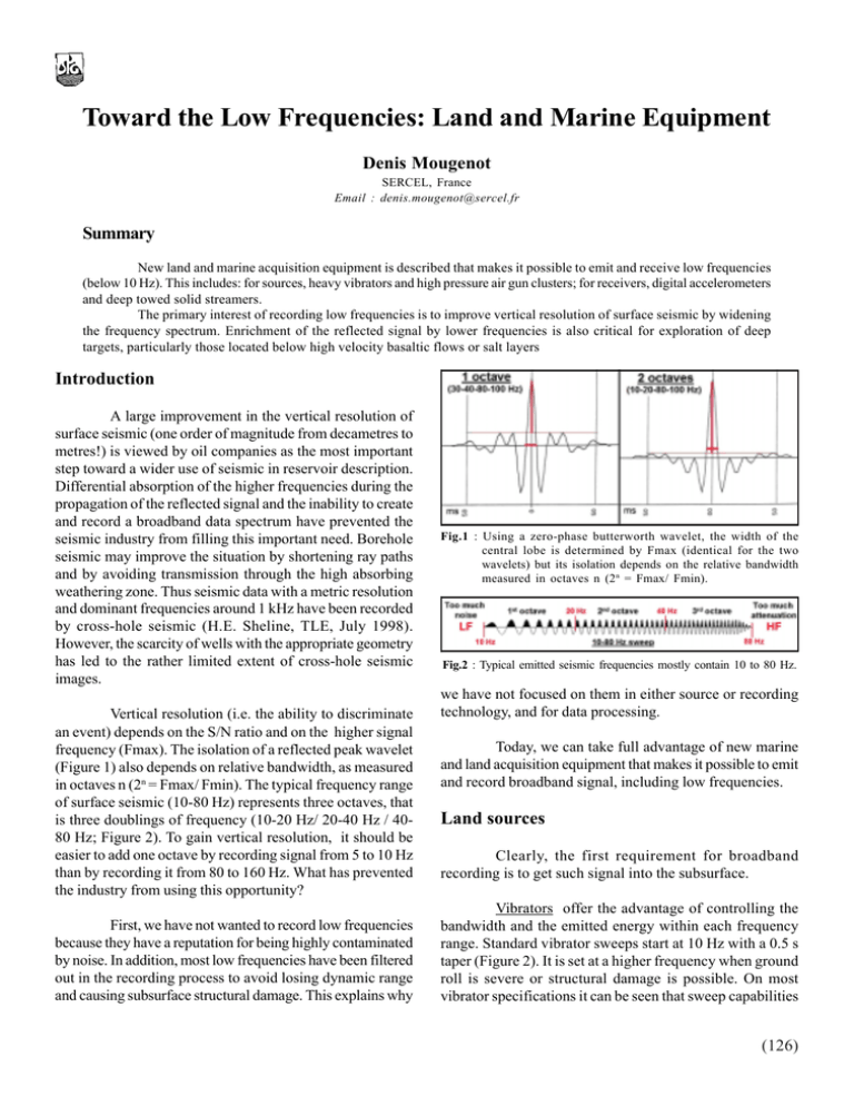
Toward the Low Frequencies: Land and Marine Equipment Denis Mougenot SERCEL, France Email : denis.mougenot@sercel.fr Summary New land and marine acquisition equipment is described that makes it possible to emit and receive low frequencies (below 10 Hz). This includes: for sources, heavy vibrators and high pressure air gun clusters; for receivers, digital accelerometers and deep towed solid streamers. The primary interest of recording low frequencies is to improve vertical resolution of surface seismic by widening the frequency spectrum. Enrichment of the reflected signal by lower frequencies is also critical for exploration of deep targets, particularly those located below high velocity basaltic flows or salt layers Introduction A large improvement in the vertical resolution of surface seismic (one order of magnitude from decametres to metres!) is viewed by oil companies as the most important step toward a wider use of seismic in reservoir description. Differential absorption of the higher frequencies during the propagation of the reflected signal and the inability to create and record a broadband data spectrum have prevented the seismic industry from filling this important need. Borehole seismic may improve the situation by shortening ray paths and by avoiding transmission through the high absorbing weathering zone. Thus seismic data with a metric resolution and dominant frequencies around 1 kHz have been recorded by cross-hole seismic (H.E. Sheline, TLE, July 1998). However, the scarcity of wells with the appropriate geometry has led to the rather limited extent of cross-hole seismic images. Vertical resolution (i.e. the ability to discriminate an event) depends on the S/N ratio and on the higher signal frequency (Fmax). The isolation of a reflected peak wavelet (Figure 1) also depends on relative bandwidth, as measured in octaves n (2n = Fmax/ Fmin). The typical frequency range of surface seismic (10-80 Hz) represents three octaves, that is three doublings of frequency (10-20 Hz/ 20-40 Hz / 4080 Hz; Figure 2). To gain vertical resolution, it should be easier to add one octave by recording signal from 5 to 10 Hz than by recording it from 80 to 160 Hz. What has prevented the industry from using this opportunity? First, we have not wanted to record low frequencies because they have a reputation for being highly contaminated by noise. In addition, most low frequencies have been filtered out in the recording process to avoid losing dynamic range and causing subsurface structural damage. This explains why Fig.1 : Using a zero-phase butterworth wavelet, the width of the central lobe is determined by Fmax (identical for the two wavelets) but its isolation depends on the relative bandwidth measured in octaves n (2n = Fmax/ Fmin). Fig.2 : Typical emitted seismic frequencies mostly contain 10 to 80 Hz. we have not focused on them in either source or recording technology, and for data processing. Today, we can take full advantage of new marine and land acquisition equipment that makes it possible to emit and record broadband signal, including low frequencies. Land sources Clearly, the first requirement for broadband recording is to get such signal into the subsurface. Vibrators offer the advantage of controlling the bandwidth and the emitted energy within each frequency range. Standard vibrator sweeps start at 10 Hz with a 0.5 s taper (Figure 2). It is set at a higher frequency when ground roll is severe or structural damage is possible. On most vibrator specifications it can be seen that sweep capabilities (126) 6th Internatiuonal Conference & Exposition on Petroleum Geophysics "Kolkata 2006" start at 5 Hz, but generally this frequency is not sustained and at full drive. This restriction in the low frequency start is related to the displacement D (stroke) of the vibrator mass M that is limited by the available hydraulic flow. Since D = HPF/Mω² (ω = 2πf), the displacement of the vibrator mass increases with lower frequencies and higher hydraulic peak force (HPF). However, the use of a bigger mass limits the necessary displacement for low frequency emissions. At the same time, such a big mass improves the mass-to-baseplate weight ratio and extends vibrator’s ability to emit the high frequencies. With Sercel’s Nomad 90T heavy vibrators (97,350 lbf), the lowest sustainable frequency at 75% drive is 5 Hz. The stroke is 10 cm and the mass-to-baseplate ratio 3.2 (7.1 T / 2.2 T). This vibrator design makes high resolution seismic possible by producing a broadband sweep. The range between low and high frequencies is close to 6 octaves (5 –250 Hz). Its’ ground force (90,000 lbf) is large enough to use this vibrator as a point source. low frequencies are highly attenuated (-20 dB) from a peak amplitude that occurs between 10 & 30 Hz. Fig. 4 : Shot point (SP) recorded from explosive by the vertical component of a digital sensor (center). FK spectrum (left) from the whole SP displays the very low frequency content of the ground roll (GR). Amplitude spectrum (right) from a small window within the reflected signal (Si) shows a lack of low frequencies It seems that most of the explosive energy is used to produce fracturing, gas heat and surface waves. In addition, the transformation into elastic waves should be highly dependant on the properties of the borehole environment and on the nature of the explosive (speed, pressure & gas generation). Longer explosions as provided by new dual composition explosives developed for seismic application improve the transfer of energy into the formation. From analysis of the signal, both low and high frequencies increase (+12 dB) and the peak amplitude is shifted towards low frequencies (J. Quigley et al., SEG 2004). Marine guns Fig. 3 : the Nomad 90T heavy vibrator (97,350 lbf) offers the highest mass-to-baseplate ratio (3.2 = 7.1 T / 2.2 T). Explosive sources are known to produce broadband signal including low frequencies. However, little has been published to show the relationship between the type of explosive, the charge, the depth of the source and the frequency content. Crews often rely on rules of thumb (bigger and deeper charges create more low frequency energy) more or less validated by field testing. As can be seen in Figure 4, by recording the conventional charges used for seismic exploration (1-10 Kg at 10-30 m depth) with a Sercel DSU digital accelerometer, there are little low frequencies left in the reflected signal. An FK diagram on the whole shot point evidences the lower frequencies emitted (down to 2 Hz) are primarily ground-roll (GR). An amplitude spectrum of the reflected signal (Si) shows the A standard arrays of air-guns (3 strings of 10 guns, 3,500 cu.in.) is band limited below 10-12 Hz. Its’ ability to produce lower frequencies may be improved by increasing the air pressure used in the guns (Figure 5). While the industry uses guns and compressors at a typical pressure of 138 bar (2,000 psi), Sercel’s G.GUN is designed for standard use at a pressure of 207 bar (3,000 psi). Fig. 5 : G.Gun parallel cluster far field amplitude spectrum and its variation with pressure. (127) The lowest frequency (Fmin) of the emission also depends on the individual volume of the guns. Since the dominant bubble period (T) of a gun signature varies with the cube root of its volume, the dominant frequency of the signal, that corresponds to the minimum frequency Fmin = 1/T, decreases with increasing gun volume. As large guns are not easy to handle, it is possible to cluster identical guns to increase the bubble period. For a standard 2 x 250 cu.in. G. GUN parallel cluster at 5 m depth & 3000 psi, the dominant frequency is as low as 6 Hz (Figure 5). The effect of gun immersion on the low frequency content is not as straightforward as for the high-cut frequency that depends only on the spectral notch created by the surface ghost. This ghost has a destructive effect on the first bubble where the lower frequencies are concentrated (Z. Lunnon et al., EAGE, June 2003). Increasing the gun depth can shift the direct and the ghost bubbles of opposite polarity, potentially improving the amount of low frequency energy Independent of surface notch effects, the bubble period decreases with depth due to a greater hydrostatic pressure, that is the corresponding dominant/minimum frequency increases rather than falls (W.H. Mayne et al., Geophysics, December 1971). Fig. 6 : A 3C Digital Sensor Unit (DSU3) integrates all sensors with the field electronics and the connection to the line. The flatness and stability of the phase & amplitude responses, compared to a geophone (Figure 7), seem to be an important advantage in recording low frequencies. However, a geophone can be compensated in processing for its low frequency attenuation, assuming this attenuation (and the corresponding resonant frequency) is stable (in practice there is a few percent variation). Probably, the most interesting feature of a digital accelerometer to record low frequencies is its lower distortion (-90 dB compared to -62 dB for the geophone) that helps preserve signal by resisting interference from the strong harmonics of the surface noise. A different way to enhance low-frequency signal content has been tested. It involves delaying the different guns of an array in order to synchronize the bubbles instead of the first pressure peaks (Z.C. Lunnon et al., First Break, December 2003). This technique is a good way to improve low frequency and it has proven useful for deep crustal and sub-basalt imaging (J. Maresh and R.S. White, First Break, May 2005). However, it is detrimental for the highfrequency content of the source and it deteriorates seismic resolution in the upper sedimentary layers. Digital accelerometers New MEMS based digital accelerometers have been developed over the past few years for the seismic industry (Figure 6). They offer a broadband linear phase and amplitude response that extends from 0 Hz (DC) to 800 Hz (Figure 7). These accelerometers make it possible to record frequencies below 10 Hz without attenuation, including the direct current (DC) which is related to gravity acceleration. This gravity vector is a useful reference for sensitivity control and tilt measurement. Fig. 7 : Phase & amplitude response of a MEMS-based digital sensor (acceleration) compared to a 10 Hz geophone (velocity). Low frequency analog sensors Coiled geophones are manufactured with resonant frequencies (Fr) that range from 2 Hz to 35 Hz. These depend on the spring/coil rigidity (K) and on the mass (M) of the magnet: Fr = (K/M)1/2 / 2π. Since amplitude is attenuated (128) 6th Internatiuonal Conference & Exposition on Petroleum Geophysics "Kolkata 2006" below this resonant frequency at a rate of 12 dB/octave (Figure 7), Fr is selected at 10 Hz or above to attenuate the low frequency surface noise. Lower resonant frequency geophones that use a larger mass are cumbersome, more expensive and they are more sensitive to tilt. They are seldom used in the field except for occasional refraction surveys. Piezoelectric hydrophones as used in marine streamers have a low frequency roll-off beginning at 3 Hz with an attenuation of 6 dB/octave down to DC. Therefore, these hydrophones can record low frequencies, limitations being more on the source side. Hydrophone capabilities may be extended below 0.5 Hz, with the drawback of more electric and swell noise. Such hydrophones are able to measure the wave height, a parameter used to de-ghost seismic data (E. Kragh et al., EAGE 2004). Fig. 8 : Band pass filtering of the upgoing signal depends on the streamer depth due to the surface ghost interference. Deeper the streamer less is the attenuation of the lower frequencies. Application Deep towed solid streamers Solid streamers are designed to minimize mechanical noise and decreases weather downtime compared to fluid-filled streamers ( M. Brink and J. Spackman, EAGE, June 2005). They are not prone to bulge waves which cause low frequency noise due to internal fluid flow. Their advantage to record low frequencies is not only related to better S/N but also to a superior depth control due to their neutral buoyancy. The streamer depth below the sea surface has a pronounced effect on the frequency content. Increased streamer depth will result in lower-frequency data, all else being equal. The reason for this is that the sea surface is a perfect reflector at seismic frequencies. It creates a phase inverted down-going ghost that interferes with the direct upgoing signal with a delay that depends on immersion (like for the gun emitted signal, see above). It has been demonstrated that, whatever the tow depth, the relative bandwidth is always 2.32 octaves (cited in J. Maresh and R.S. White, First Break, May 2005). Therefore, the deeper the streamer, the lower the high frequency notch and the steeper the low frequency roll-off, to keep constant the relative bandwidth (Figure 8). At 6 m depth, the high frequency notch occurs at Fmax = Vwater / 2 x depth = 1500 / 12 = 125 Hz and the low frequency one starts at Fmin = Fmax / 2*2.32 = 125 / 5 = 25 Hz. At 10 m depth, Fmax = 75 Hz and Fmin = 15 Hz. At 22.5 m depth, Fmax = 60 Hz and Fmin = 12 Hz. Although deep towed streamers offer a suitable low frequency band-pass, it is worth mentioning that it is also necessary to tune the guns so as to produce energy in the same low frequency band. The suitability of surface seismic for deep target exploration (say below 5,000 m) is limited by attenuation and scattering of the wave front. Due to their ability to carry more energy deeper into the subsurface with fewer attenuation and scattering, low frequencies are less affected by these propagation effects. Another limitation is our ability to reconstruct the true raypaths and to properly gather traces reflected by the same common reflection point. That ability decreases with increasing depth and associated subsurface complexities. Low frequencies with a larger Fresnel zone are less sensitive to these imperfections and easiest to stack. As an example, it has been demonstrated that low frequencies are the key for imaging sedimentary layers below high velocity bodies like basaltic flows (A. Ziolkowski et al., Geophysical Prospecting, 2003) and salt pillows (M.S. Egan and N. Moldoveanu, SEG, November 2005). Conclusions The success of seismic in recording low frequencies and improving vertical resolution is not yet common practice. For this to become a standard activity many obstacles must be overcome. The steepest one is the surface noise that contaminates low frequencies. Solving this requires dense spatial sampling and high fold coverage. But once that decision is made, the ability to record broad band data, properly sampled, is a reality using today’s recording systems which are capable of handling very large channel count effectively. It is also important to realize that standard (129) processing modules are not often designed to preserve low frequencies due to hidden low-cut filters and to short filtering operators. Improved vertical resolution will facilitate exploration of deep targets and provide better seismic-towell correlation. By contributing more efficiently to reservoir description, seismic should be able to confirm its future as a cost-effective tool to enhance oil & gas production. Acknowledgment The author is grateful to Daniel Boucard, Michel Gros and Malcolm Lansley from Sercel for their useful explanations about low frequency capability of seismic equipments (130)


