Skylark Contour® dimmers and fan controls
advertisement
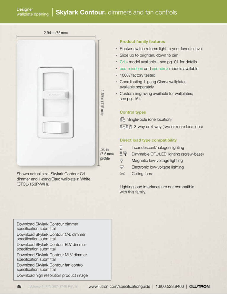
Designer wallplate opening Skylark Contour dimmers and fan controls ® 2.94 in (75 mm) Product family features Rocker switch returns light to your favorite level • Slide up to brighten, down to dim • C•L® model available—see pg. 01 for details • eco-minderTM and eco-dim® models available • 100% factory tested • Coordinating 1-gang Claro® wallplates available separately • 4.69 in (119 mm) Custom engraving available for wallplates; see pg. 164 • Control types Single-pole (one location) 3-way or 4-way (two or more locations) Direct load type compatibility .30 in (7.6 mm) profile Shown actual size: Skylark Contour C•L dimmer and 1-gang Claro wallplate in White (CTCL-153P-WH). Incandescent/halogen lighting Dimmable CFL/LED lighting (screw-base) Magnetic low-voltage lighting Electronic low-voltage lighting Ceiling fans Lighting load interfaces are not compatible with this family. Download Skylark Contour dimmer specification submittal Download Skylark Contour C•L dimmer specification submittal Download Skylark Contour ELV dimmer specification submittal Download Skylark Contour MLV dimmer specification submittal Download Skylark Contour fan control specification submittal Download high resolution product image 89 Volume 1 P/N 367-1746 REV B www.lutron.com/specificationguide | 1.800.523.9466 | Designer wallplate opening Skylark Contour dimmers and fan controls ® Available finishes Use BOLD color code in model number (Example: CT-600P-IV) Gloss finishes* WH White LA Light Almond AL Almond GR Gray BR Brown BL Black IV Ivory SS Stainless Steel *Coordinating wallplates only available separately. For wallplate information, see pg. 169. | 1.800.523.9466 | www.lutron.com/specificationguide Volume 1 P/N 367-1746 REV B 90 Designer wallplate opening Skylark Contour dimmers and fan controls ® Dimmers with on/off switch C•L® dimmers provide reliable dimming of dimmable CFLs/LEDs, as well as halogens and incandescents • eco-dim® model guarantees at least 15% energy savings and triples lamp life compared to a standard switch†­ • Incandescent/halogen or Magnetic low-voltage dimmers Dimmers 3-way/single-poleCT-103P-XX1 120 V 600 VA (1000 W) The stated VA (Volt-Ampere) rating includes the magnetic transformer heat losses and the lamp load. The stated W (Watt) rating is the maximum lamp wattage based on assumed 20% transformer loss. Electronic low-voltage dimmers* Incandescent/halogen dimmers Dimmable CFL (screw-base) dimmers Dimmable LED (screw-base) dimmers C•L dimmers 3-way/single-poleCTCL-153P-XX1 120 V 600 W (INC) 150 W (CFL or LED) Dimmers 3-way/single-poleCTELV-303P-XX1 120 V 300 W Certain LED drivers are dimmable using an ELV dimmer; visit www.lutron.com/LED for more information. Visit www.lutron.com/dimcflled for an approved list of dimmable CFL/LED bulbs, and how to calculate wattage when mixing lamp types. Incandescent/halogen dimmers Dimmers Single-poleCT-600P-XX1 120 V 600 W 3-wayCT-603P-XX1 120 V 600 W eco-dim dimmer† Multi-location/single-poleCT-603PG-XX 2 120 V 600 W XX1:Gloss color codes, see pg. 90 XX 2:Gloss White (WH), Light Almond (LA), Almond (AL) and Ivory (IV), see pg. 90 (Wallplates not included. Order separately, see pg. 169) 91 Volume 1 P/N 367-1746 REV B Satin Colors All models must be derated if ganged unless otherwise noted, see pg. 179. For more information on Lutron ballasts, visit www.lutron.com/ballasts. *Requires neutral wire connection. †Maximum light output of 85% guarantees 15% energy savings over standard switches. www.lutron.com/specificationguide | 1.800.523.9466 | Designer wallplate opening Skylark Contour dimmers and fan controls ® Connections overview Load connections* Incandescent/ Halogen Incandescent/ Halogen Dimmer Dimmable CFL/LED (screw-base) C •L® Dimmer C •L Dimmer Magnetic Low-Voltage Electronic Low-Voltage MLV Transformer (by others) ELV Transformer (by others) MLV Dimmer ELV Dimmer Ceiling Fan Fan Control Control types (for 2 or more locations) Dim from one location, switch from the others Light Source 3-way Dimmer 3-way Switch Light Source Download complete Connection Diagrams 93 Volume 1 P/N 367-1746 REV B 3-way Dimmer 4-way Switch (1 or more) 3-way Switch For more information on ballasts, visit www.lutron.com/ballasts. For more information on LED drivers, visit www.lutron.com/LED. *For illustration purposes only. Consult model number pages for specific voltage and capacity information. www.lutron.com/specificationguide | 1.800.523.9466 | Appendix | Mounting, ganging, and derating Mounting requirements and how to understand ganging and derating Individual devices Individual dimmers, switches, wall sensors, and accessories typically mount in standard 1-gang electrical boxes (fig. A). Standard ganging Ganging is the side-by-side mounting of two or more dimmers or accessory devices under a multi-gang wallplate. (fig. B-D) A1-gang box (W: 2 in x H: 3 in x D: 2.5 in) B2-gang box (W: 4 in x H: 3 in x D: 2.5 in) Standard multi-gang installation: • Uses standard multi-gang electrical backboxes • Uses standard multi-gang wallplates Requires fins to be removed from dimmers for proper spacing (“Fins Broken” ganging) C3-gang box (W: 6 in x H: 3 in x D: 2.5 in) • May require derating (i.e., reduction of dimmer capacity due to fin removal); see derating tables, pg. 181 • Custom Architectural ganging Architectural dimmers, switches and accessories may be ganged without derating (fig. E), via custom Architectural multi-gang: • May require customized, wider-thanstandard wallplates • • • D4-gang box (W: 8 in x H: 3 in x D: 2.5 in) E(2) 1-gang boxes with 3/4 in spacer May require wider-than-standard electrical backboxes Allows full capacity (“No Fins Broken”) ganging Required for Nova® dimmers and for larger width (high capacity) architectural controls Visit www.lutron.com/customganging for additional information • Light load power interfaces (pg. 185) Interfaces typically mount to a standard electrical junction box (fig. F); must be mounted within 7 degrees of vertical. Maximum output: 5.1 in x 6.3 in. Interfaces project 1.2 in in front of box. Ceiling/wall mount sensors (pgs. 43 and 147) Wireless ceiling mount Radio Powr SavrTM sensors (fig. G) mount to brackets provided with sensor using adhesive strips or mounting hardware provided. 179 Volume 1 P/N 367-1746 REV B FJunction box (W: 4 in x H: 4 in x D: 2.5 in) GWireless sensor mounting bracket (3.2 in diameter footprint, mounting brackets are spaced 1.8 in) www.lutron.com/specificationguide | 1.800.523.9466 | Appendix | Visual index Maximum Wattage Additional Features Voltage Indicated by the first two, three, or four numbers: Letters that follow the wattage (prior to the hyphen) indicate other special features: Operating voltage is 120 V unless indicated 150 200 300 600 10 or 1000 1500 2000 5 6 8 150 Watts 200 Watts 300 Watts 600 Watts 1000 Watts 1500 Watts 2000 Watts 5 Amp 6 Amp 8 Amp 10 3 Single-pole/3-way/ multi-location Indicated by the number at the end of the wattage: 0Single-pole 33-way MMulti-location 2 Dual Control * 277 270 V PPreset NL Night Light H Clamshell Packaging W With Wallplate DC Dimmable Compact Fluorescent - P 277 - WH Color Suffix* To order the specific color desired, add the color suffix to the end of the model number: WHWhite IVIvory ALAlmond LA Light Almond BEBeige TPTaupe GRGray SISienna BRBrown BLBlack BN Bright Nickel BC Bright Chrome CLA Clear Anodized Aluminum SC Satin Chrome SN Satin Nickel QZ Antique Bronze BB Bright Brass BRABrass Anodized Aluminum SB Satin Brass QB Antique Brass BLA Black Anodized Aluminum SWSnow LSLimestone BIBiscuit ESEggshell PDPalladium STStone BGBluestone PLPlum SG Sea Glass TQTurquoise GSGoldstone DS Desert Stone GBGreenbriar MS Mocha Stone TCTerracotta HTHot MRMerlot MNMidnight SS Stainless Steel Some colors not available with certain families. Consult family pages or contact customer service. | 1.800.523.9466 | www.lutron.com/specificationguide Volume 1 P/N 367-1746 REV B 210
