Shunt Reactors for Voltage Cont
advertisement

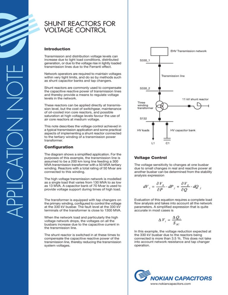
SHUNT REACTORS FOR VOLTAGE CONTROL APPLICATION NOTE Introduction Transmission and distribution voltage levels can increase due to light load conditions, distributed generation, or due to the voltage rise in lightly loaded transmission lines due to the Ferranti effect. Network operators are required to maintain voltages within very tight limits, and do so by methods such as shunt capacitor banks and tap changers. Shunt reactors are commonly used to compensate the capacitive reactive power of transmission lines and thereby provide a means to regulate voltage levels in the network. These reactors can be applied directly at transmission level, but the cost of switchgear, maintenance of oil-cooled iron core reactors, and possible saturation at high voltage levels favour the use of air core reactors at medium voltage. This note describes the voltage control achieved in a typical transmission application and some practical aspects of implementing a shunt reactor connected to the tertiary winding of a transmission power transformer. Configuration The diagram shows a simplified application. For the purposes of this example, the transmission line is assumed to be a 200 km long line feeding a 300 MVA transmission transformer with a 50 MVA tertiary winding. Reactors with a total rating of 50 Mvar are connected to this winding. Voltage Control The voltage sensitivity to changes at one busbar due to small changes in real and reactive power at another busbar can be determined from the stability analysis expression The high voltage transmission network is modelled as a single load that varies from 130 MVA to as low as 13 MVA. A capacitor bank of 70 Mvar is used to provide voltage support during times of high load. The transformer is equipped with tap changers on the primary winding, configured to control the voltage at the 330 kV busbar. The fault level at the 330 kV terminals of the transformer is close to 1300 MVA. Evaluation of this equation requires a complete load flow analysis and takes into account all the network parameters. A simplified expression that is quite accurate in most cases is When the network load and particularly the high voltage network drops, the voltages on all the busbars increase due to the capacitive current in the transmission line. The shunt reactor is switched in at these times to compensate the capacitive reactive power of the transmission line, thereby reducing the transmission system voltages. In this example, the voltage reduction expected at the 330 kV busbar due to the reactors being connected is more than 3.5 %. This does not take into account network resistance and tap changer operation. www.nokiancapacitors.com Full load, no capacitor bank Full load, with capacitor bank Light load, no reactors Light load, with reactors S132 S330 0.78 0.97 1.14 0.92 0.94 0.99 1.02 0.99 The actual voltage reduction as a result of the reactors is therefore 2.7 % at the EHV busbar. The load-voltage curve below is from a comprehensive study of a real transmission system that takes into account all possible load levels in the network and the operation of all tap changers and shunt capacitor banks. The improvement in voltage level at all load levels is clearly visible. The reactor should be equipped with over current and earth fault protection monitoring the line side current. In cases where the reactors are connected to the tertiary winding of a transformer, it is most likely that the reactor feeder will be included in the transformer differential protection. Differential protection of the reactor can be achieved by splitting each phase into two legs and monitoring the unbalance current in the star point. This method provides extremely fast and sensitive protection of the reactor windings, specifically in terms of interturn faults. 1,1 Reactors switched out Reactors switched in Busbar S330_2 voltage (pu) APPLICATION NOTE The table below shows the impact on voltage levels in per unit for various operating modes. 1,08 1,06 1,04 1,02 1600 Switching of reactors 1800 2000 2200 2400 System load (MW) The next sections will briefly discuss some implementation issues associated with shunt reactors. Protection and earthing IEEE C37 provides comprehensive guidelines for switching requirements of reactors. One of the most important aspects of switching reactors is current chopping caused by forcing reactor current to zero before the zero crossing. This could result in high voltage across breaker poles. In most applications of shunt reactors in EHV and HV systems, the star point of the reactors are connected to earth, whereas MV shunt reactors are generally not earthed. The introduction of copper/chromium contact material in vacuum circuit breakers overcame the problem with over-voltages as a result of switching as long as other precautions are also taken and the circuit breaker is adequately rated for the specific application. If the star point of the transformer tertiary winding is not earthed, then earthing the reactor would assist in detecting earth faults in this zone. However, such earth fault detection can also be made by means of voltage measurement, with an earthed star primary and open delta secondary voltage transformer used to detect earth faults on the network supplied by the tertiary winding. The oscillation frequency and magnitude is determined by the inductances and stray capacitance associated with the reactor, the circuit breaker and the network components in close proximity to the circuit breaker. These capacitances are generally very low, resulting in high frequency switching transients that are especially harsh on circuit breaker contact surfaces. www.nokiancapacitors.com The effect of such surge capacitors is shown in the graph below. The frequency of the switching transient is reduced from more than 40 kHz to less than 6 kHz by the introduction of a 100 nF capacitor between phase and earth. The reduced oscillation frequency results in less contact wear and therefore longer life of the circuit breaker, as well as reduced reactor inter-turn stress levels. Practical considerations The following additional aspects should be taken into account when studying and designing shunt reactor installations: 1) Most installations of the kind described here contain more than one shunt reactor on the transformer tertiary, in order to provide fine voltage control. 2) Some form of control is required to operate the various steps, and this control should take into account the control system of any tap changer that may be present on the transformer primary or secondary. 2 Without surge capacitor With surge capacitor 1,5 Current (pu) APPLICATION NOTE The oscillation frequency can be reduced by means of surge capacitors placed between the reactor and the circuit breaker. 3) Surge arrestors are commonly applied to the reactor and transformer tertiary terminals to avoid excessive voltages during switching. 1 0,5 4) Appropriate magnetic and electrical clearances between the reactors and other substation equipment must be observed, and all footings must be designed for use together with air core reactors. 0 -0,5 -1 0 0,5 1 1,5 2 Time (s) Ferro-resonance There is a theoretical possibility that ferro-resonance may occur between the various capacitances including stray capacitances to the tertiary 11 kV busbar and the non-linear ferro-magnetic inductance of voltage transformer cores present on the 11 kV system. Ferro-resonance is often hard to predict and depends on a number of parameters. However, due to the non-linear nature of the resonant inductance, a wide range of capacitance can cause ferro-resonance at a particular frequency. Ferro-resonance is worse when single- or two-phase switching is encountered, and typically occurs in unloaded systems with low resistive loading and / or losses. The phenomenon seldom occurs in balanced systems. High source impedance (low fault level) can also contribute to ferro-resonance. Conclusion Modern transmission systems are operated closer to security limits and the pressure to optimise power transfer for economic reasons is constantly increasing. The ability to control transmission voltages to the extent possible with shunt reactors is very attractive from a commercial and technical point of view. Nokian Capacitors can assist with detailed system studies to determine the feasibility of such installations, and provide all required electrical, mechanical and control design parameters of shunt reactor installations. Ferro-resonance is normally avoided by applying a small load to the secondary of the transformer causing this phenomenon. In the case of voltage transformers, ferro-resonance is prevented by applying a small resistive load typically about 30 % of the voltage transformer rating. www.nokiancapacitors.com


