Flow controller - IMI Hydronic Engineering
advertisement

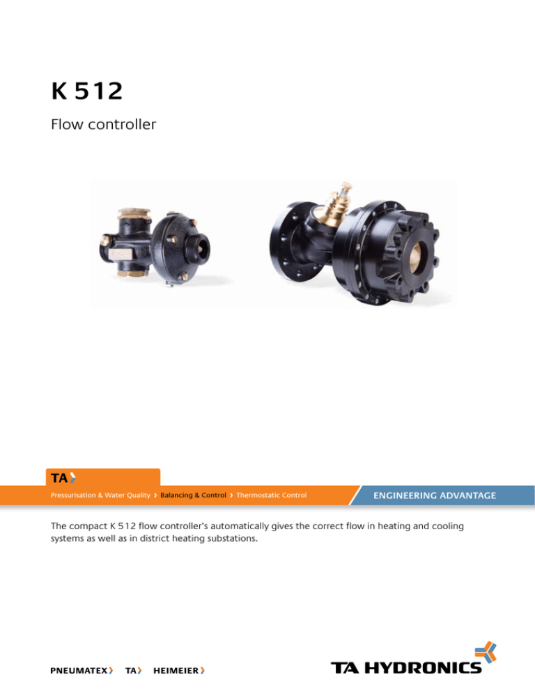
K 512 Flow controller Pressurisation & Water Quality Balancing & Control Thermostatic Control ENGINEERING ADVANTAGE The compact K 512 flow controller’s automatically gives the correct flow in heating and cooling systems as well as in district heating substations. Flow controllers - K 512 Inline design Inline flow allows high pressure drops without noise. Adjustable flow Ensures the design flow. Compatibility with KTx valves Sharing the same body makes upgrading straightforward. Technical description Application: Heating and cooling systems. District heating substations. Temperature: Max. working temperature: 140°C Min. working temperature: -10°C Functions: Automatic flow limitation Media: Water or neutral fluids, water-glycol mixtures. Dimensions: DN 15-125 Material: Valve body: Ductile iron EN-GJS-400-18LT Diaphragms and gaskets: EPDM Pressure class: PN 25 DN 65-125: PN 16 and PN 25 Surface treatment: Electrophoretic painting. Max. differential pressure (ΔpV): 1600 kPa = 16 bar Marking: TA, DN, PN, Fc, Kvs, GGG-40.3 and flow direction arrow. Pressure drop in the throttle (Fc): 12 kPa, 20 kPa and 40 kPa. Flanges: DN 15-50: According to EN-1092-2:1997, type 16. DN 65-125: According to EN-1092-2:1997, type 21. 2 Flow controllers - K 512 Operating function The throttle (2) for flow adjustment and inline flow controller (6) are built in series in one valve body (7). Pressure upstream of the throttle acts through internal capillary pipe (V+) to one side of diaphragm (8) in the flow controller and attempts to close it. Pressure downstream of the throttle acts through another internal impulse to the other side of the diaphragm and attempts to open the valve together with the spring force. The accuracy of flow regulation is practically independent on the pressures upstream and downstream of the regulator. V+ 1 2 3 4 9 5 6 8 1. Fixing nut 2. Throttle 3. Holes for plombing (throttle) 4. Holes for plombing (valve body) 5. Venting screws 6. Flow controller 7. Valve body 8. Diaphragm 9. Plug 7 Sizing 1. Select the smallest size for the flow you need according to qmax in the product tables. 2. Check that the available Δp is lager than the sum of the pressure drops calculated according to the formula: ( ∆pmin = Fc + 0.01 q ) Kvd 2 [l/h, kPa] Installation Installation in supply or return pipe. Flow direction is shown by the arrow on the valve body. Installation of a strainer upstream of the valve is recommended. When filling, vent the body by using the venting screws. Instead of the plug R1/4 you can install drain valve or measurement point for pressure or temperature measurement. Normal pipe fittings Try to avoid mounting taps and pumps immediately before the valve. Application example STAD (STAF) K 512 3 Flow controllers - K 512 Setting Presetting of the maximum flow Release the fixing nut (1). Turn the flow setting screw (2) clockwise to position of 0,0 turns. Turn the flow setting screw anticlockwise the corresponding number of turns according to flow chart. Tighten the fixing nut. The flow setting can be plomed by using holes (3a and 3b) on flow setting screw and the valve body. 3a 1 2 4 a Measure the flow on the balancing valve STAD using the balancing instrument TA-SCOPE or measuring instrument TA-CMI. b Adjust the throttle until you measure the required flow on the TA-SCOPE or TA-CMI. c Lock the fixing nut. When you lock the nut please hold the throttle in place with an allen key. 3b Table - Example: Valid table is delivered with each valve. ,0 ,1 ,2 ,3 ,4 ,5 ,6 ,7 ,8 ,9 Alternative: a Take the presetting value from the table which is packed with the valve. b Open the throttle anti-clockwise. The preset value (e.g. 3,4) means that you open the valve three complete turns. After that turn until the figure 4 fits the red mark on the valve body. c Lock the fixing nut. When you lock the nut hold the throttle in place with an allen key. Position - Einstellung 0, 0 1 ,0 2, 0 3 ,0 4, 0 57 19 8 4 35 656 80 4 71 22 2 4 57 671 81 5 85 24 5 4 79 686 82 5 99 26 9 5 01 700 83 6 11 3 2 93 523 715 84 6 12 8 3 17 546 730 85 7 14 2 3 40 568 745 86 7 15 6 3 64 590 760 87 8 17 0 3 88 612 774 88 8 18 4 4 11 634 789 89 9 Flow - Volumenstrom (l/h) p1=4bar p2=3bar ∆p=1bar ∆p < >> 1 bar ∆ ⇒ Flow = ≈ Articles DN 15-50 PN 25 ØD Article No DN d D L Kvd qmax [m3/h] Kg Fc = 12 kPa 52 756-720 52 756-725 52 756-740 15/20 25/32 40/50 R1 R1 1/4 R2 90 105 138 110 150 190 4,1 16 35 0,9 2,8 7,0 1,3 2,9 4,5 Fc = 20 kPa 52 756-820 52 756-825 52 756-840 15/20 25/32 40/50 R1 R1 1/4 R2 90 105 138 110 150 190 4,1 16 35 1,1 4,0 10 1,3 2,9 4,5 Fc = 40 kPa 52 756-920 52 756-925 52 756-940 15/20 25/32 40/50 R1 R1 1/4 R2 90 105 138 110 150 190 4,1 16 35 1,5 6,5 14 1,3 2,9 4,5 d d L → = Flow direction Kvd = Is the Kv value of the differential pressure control component when fully open, used to calculate the minimum pressure drop necessary for the valve to operate according to the formula found under “Sizing”. 4 Flow controllers - K 512 DN 65-125 DN 65-125 are flanged and do not need any separate connections. PN 25 (DN 65-80 also fit PN 16 flanges) Article No DN D L Kvd qmax [m3/h] Kg Fc = 12 kPa 52 773-565 52 773-580 52 773-590 52 773-591 65 80 100 125 220 220 320 320 290 310 350 400 70 70 100 150 15 18 32 38 20 22 54 55 Fc = 20 kPa 52 773-665 52 773-680 52 773-690 52 773-691 65 80 100 125 220 220 320 320 290 310 350 400 70 70 100 150 20 24 40 50 20 24 50 55 Fc = 40 kPa 52 773-765 52 773-780 52 773-790 52 773-791 65 80 100 125 220 220 320 320 290 310 350 400 70 70 100 150 30 34 55 70 20 24 50 55 Article No DN D L Kvd qmax [m3/h] Kg Fc = 12 kPa 52 773-290 52 773-291 100 125 320 320 350 400 100 150 32 38 54 55 Fc = 20 kPa 52 773-390 52 773-391 100 125 320 320 350 400 100 150 40 50 50 55 Fc = 40 kPa 52 773-490 52 773-491 100 125 320 320 350 400 100 150 55 70 50 55 ØD L PN 16 → = Flow direction Kvd = Is the Kv value of the differential pressure control component when fully open, used to calculate the minimum pressure drop necessary for the valve to operate according to the formula found under “Sizing”. 5 Flow controllers - K 512 Connections d1 d2 With female thread Threads according to ISO 228 L1 d1 d2 With male thread Threads according to ISO 7 d1 For welding L1 d2 d1 ØD EAN d1 d2 L1* 52 759-015 52 759-020 52 759-025 52 759-032 52 759-040 52 759-050 7318793546609 7318793546708 7318793546807 7318793546906 7318793547002 7318793547101 G1 G1 G1 1/4 G1 1/4 G2 G2 G1/2 G3/4 G1 G1 1/4 G1 1/2 G2 26 32 47 52 52 64,5 Article No EAN d1 d2 L1* G1 G1 G1 1/4 G1 1/4 G2 G2 R1/2 R3/4 R1 R1 1/4 R1 1/2 R2 34 40 40 45 45 50 52 759-115 52 759-120 52 759-125 52 759-132 52 759-140 52 759-150 L1 ØD Article No With flange Flange according to EN-1092-2:1997, type 16. L1 Article No EAN d1 D L1* 52 759-315 52 759-320 52 759-325 52 759-332 52 759-340 52 759-350 7318793547200 7318793547309 7318793547408 7318793547507 7318793547606 7318793547705 G1 G1 G1 1/4 G1 1/4 G2 G2 20,8 26,3 33,2 40,9 48,0 60,0 37 42 47 47 47 52 Article No EAN d1 d2 D L1* 52 759-515 52 759-520 52 759-525 52 759-532 52 759-540 52 759-550 7318793547804 7318793547903 7318793548009 7318793548108 7318793548207 7318793548306 G1 G1 G1 1/4 G1 1/4 G2 G2 M12 M12 M12 M16 M16 M16 95 105 115 140 150 165 10 20 5 15 5 20 *) Fitting length (from the gasket surface to the end of the connection). The products, texts, photographs, graphics and diagrams in this document may be subject to alteration by TA Hydronics without prior notice or reasons being given. For the most up to date information about our products and specifications, please visit www.tahydronics.com. 6-10-20 K 512 03.2011 6

