Page 1 911400-00 Readymount Installation Instructions © Allegion
advertisement

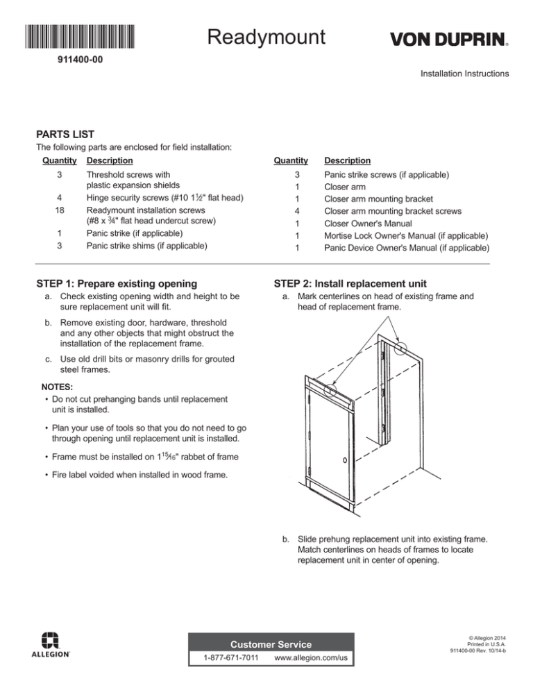
Readymount 911400-00 Installation Instructions PARTS LIST The following parts are enclosed for field installation: Quantity 3 4 18 1 3 Description Quantity Threshold screws with plastic expansion shields Hinge security screws (#10 11»2" flat head) Readymount installation screws (#8 x 3»4" flat head undercut screw) Panic strike (if applicable) Panic strike shims (if applicable) STEP 1: Prepare existing opening 3 1 1 4 1 1 1 Description Panic strike screws (if applicable) Closer arm Closer arm mounting bracket Closer arm mounting bracket screws Closer Owner's Manual Mortise Lock Owner's Manual (if applicable) Panic Device Owner's Manual (if applicable) STEP 2: Install replacement unit a. Check existing opening width and height to be sure replacement unit will fit. a. Mark centerlines on head of existing frame and head of replacement frame. b. Remove existing door, hardware, threshold and any other objects that might obstruct the installation of the replacement frame. c. Use old drill bits or masonry drills for grouted steel frames. NOTES: Do not cut prehanging bands until replacement unit is installed. Plan your use of tools so that you do not need to go through opening until replacement unit is installed. Frame must be installed on 115»16" rabbet of frame Fire label voided when installed in wood frame. b. Slide prehung replacement unit into existing frame. Match centerlines on heads of frames to locate replacement unit in center of opening. Customer Service 1-877-671-7011 www.allegion.com/us © Allegion 2014 Printed in U.S.A. 911400-00 Rev. 10/14-b STEP 3: Secure frame to existing frame STEP 4: Make final installation a. Cut and remove prehanging bands. b. Open door, remove spacers. c. Drill 5»32" dia. holes (No. 24 drill) through open holes in top and center frame hinge leaves into existing frame. It may be necessary to adjust drill size to suit existing frame material. Install No. 10 x 11»2" flat head screws in holes in hinge leaves (screws furnished). d. Drill 1»4" x 1" deep holes through holes in threshold into floor. Start plastic shields on No. 10 x 11»2" F.H. screws and insert shields/screws through holes in threshold in to 1»4" dia. holes in floor (screws and shields furnished). a. Drill 9»64" dia. holes (No. 29 drill) through countersunk holes in replacement frame into existing frame. b. Install No. 8 x 3»4" F.H. undercut screws in counter sunk, drilled holes (screws furnished). STEP 5: Complete closer installation Mount closer arm to soffit of existing frame head (screws enclosed). Refer to closer installation instruction manual for adjustments to closer. View from side View from below 2 STEP 6: Instruction for doors prepped with panic devices only Install panic device strike to soffit of existing strike jamb at centerline of panic device latch. Enclosed shims may be required for added clearance (screws furnished). TRIM INSTALLATION AND REMOVAL The information below details instructions for installing and removing glass trim for doors prepared with glass lites. Installing trim: 1. Install spring retaining clips in the opening. Keep each clip a minimum of 3" from corner. (Please see Clips & Spacer table on back page for necessary quantity needed for installation). 2. Labeled doors require a spacer channel when any cutout exceeds or is equal to 10". The spacer channels snap over the door and are located between the spring retainer clips. Do not place a spacer channel in a corner. (See chart on back page for quantity required.) 3. Install glass trim assembly on one side. Be sure the trim snaps over the spring clips. 4. Back putty and install the glass in the opening. The glass will sit on the spring clips. 5. Install the other glass trim assembly. Again, be sure the trim snaps over the spring clips. 6. Finish putty. Removing trim: 1. Starting at the clip in one corner, depress the tab located on the clip within the glass groove. Use a small screwdriver, awl or similar tool. 2. Pull and hold the trim out over the depressed spring tab. 3. Repeat operation at the next spring clip tab until trim is loose. Constantly hold pressure on the trim to ensure the trim does not snap back over the tab. Generally, the trim can be removed by releasing the spring clip tabs on two adjacent sides. Narrow lites may require releasing the spring clip tab on three sides. Retainer Clips Trim Retainer Tab Trim Retainer Tab Door Panel Space Tab Clip Securing Bars Emboss Around Glass Cutout Door Core Trim can be removed by pressing release tab down with screwdriver or similar tool at groove/clip. Trim Assembly Retainer Clip GLASS CUTTING SIZES (Maximum 1»2" thick glass) The information below details specific dimensions for ordering or replacing glass for the Retro Door. Narrow Lite Half Glass Lite 6'8" Doors Door Height 51»8" x 261»8" 2213»32" x 2823»32" 7'0" Doors 51»8" x 261»8" 2213»32" x 3223»32" 3 FIELD PAINT PROCEDURES: The Readymount door and frame are furnished with a high grade, low gloss, baked-on prime paint that provides the best possible protection against corrosion, abrasion and weather, and is an excellent base for finish paint. This is a primer, however, and requires field finishing. If the primed surface is removed or damaged, the exposed metal must be reprimed with a suitable rust inhibitive primer before top coating with a latex finish paint. The application of the paint, using either a brush, roller or spray equipment, shall be in accordance with the paint manufacturer's recommendations. If spray equipment is used, consult with the paint supplier on recommendations for correct thinner or solvents. Do not use lacquer thinner or other solvents that may react on the primer coat. AIR DRY APPLICATIONS: To obtain the best results, use the following procedures: 1. Avoid painting in extremely cold or damp weather. Suggested temperature range 50°F to 90°F. 2. Sand door surfaces lightly with No. 300 or 320 emery cloth or steel wool. 3. Clean door surfaces using a mild solvent such as mineral spirits or a mild citrus cleaner. Do not use strong cleaning agents, acids or lacquer thinner. 4. Dry door surfaces. Do not use oiled or tack rags to dry door surfaces. 5. Apply finish paint following manufacturer's recommendations. Notes: 1. Latex paints may require, depending on atmospheric conditions, up to 30 days before the paint is fully cured. 2. To avoid rusting with latex topcoat paints, it is recommended to sand and re-prime with a rust inhibitive primer any areas where the factory applied primer has been removed or scratched through. 4 For more information please call . . . 1-877-671-7011

