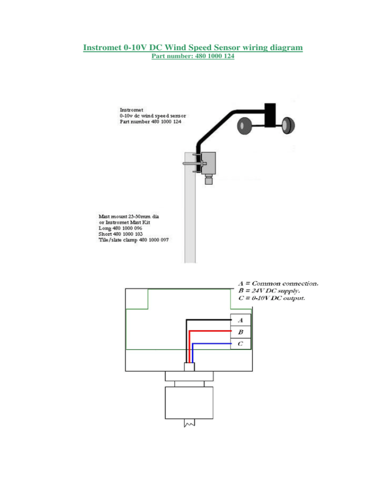
Instromet 0-10V DC Wind Speed Sensor wiring diagram
advertisement

Instromet 0-10V DC Wind Speed Sensor wiring diagram Part number: 480 1000 124 Installation Instructions Sensor wiring The three core cable should be connected to the individual sensor via the terminal block within the sensor enclosure. This can be accessed by un-doing the two screws securing the cover, where a wiring colour identification label will be found. Roof Top Wind/Temperature Sensor This unit should be mounted on a mast of 25-50mm (1-2inches) in diameter, as high and as far away as possible from chimneys, roof peaks, buildings, trees and transmitter aerials which may cause wind turbulence or interference. Where possible the roof top wind sensor should be mounted at least 2 metres above roof peaks and be secured in position. The cable from the roof top wind sensor should be run down, making sure it is properly secured. Please note! This cable should not be run in close proximity to power or transmitter cables. If it is necessary to shorten the cable, please do this when connecting the cable to the display unit. Troubleshooting Guide. You've installed your Wind sensor and find that despite careful attention to detail, it does not work as expected. The following notes may assist in getting your Wind sensor working. Nothing appears to work. Check that the power supply is connected and turned on, 24V DC . Check power cable correctly wired to the correct terminals in the sensor enclosure. Wind Speed not working Check anemometer cups are turning freely and if so wiring is correct (particularly the blue wire from the Wind Sensor) and the cable not damaged. Wind Sensor voltages Supply voltage Wind Speed Black – Red = 24V DC Black – Blue = 0-10V DC 90mph equates to 8.5V DC If all fails call service department 01692 502800 or return the sensor to us for checking or replacement. Instromet Weather Systems Ltd 10a, Lyngate Industrial Estate North Walsham Norfolk NR28 0AJ Tel: (01692) 502800 Fax: (01692) 502801 e-mail: sales@Instromet.co.uk


