POLY-FUSE® Resettable PTCs VL Series
advertisement
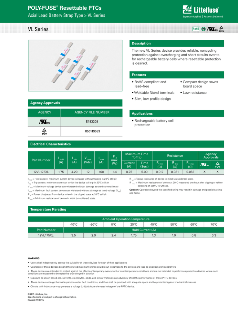
POLY-FUSE® Resettable PTCs Axial Lead Battery Strap Type > VL Series VL Series RoHS Description The new VL Series device provides reliable, noncycling protection against overcharging and short circuits events for rechargeable battery cells where resettable protection is desired. Features • RoHS compliant and lead–free • Weldable Nickel terminals • Compact design saves board space • Low resistance • Slim, low profile design Agency Approvals AGENCY AGENCY FILE NUMBER Applications • Rechargeable battery cell protection E183209 R50119583 Electrical Characteristics Part Number I hold (A) I trip (A) V max (Vdc) I max (A) Pd max. (W) 12VL175XL 1.75 4.20 12 100 1.4 Maximum Time To Trip Agency Approvals Resistance Current (A) Time (Sec.) R min (Ω) R typ (Ω) R 1max (Ω) 8.75 5.00 0.017 0.031 0.062 X X I hold = Hold current: maximum current device will pass without tripping in 20°C still air. R typ = Typical resistance of device in initial (un-soldered) state. I trip = Trip current: minimum current at which the device will trip in 20°C still air. R 1max = Maximum resistance of device at 20°C measured one hour after tripping or reflow soldering of 260°C for 20 sec. V max = Maximum voltage device can withstand without damage at rated current (I max) I max = Maximum fault current device can withstand without damage at rated voltage (Vmax) P d = Power dissipated from device when in the tripped state at 20°C still air. Caution: Operation beyond the specified rating may result in damage and possible arcing and flame. R min = Minimum resistance of device in initial (un-soldered) state. Temperature Rerating Ambient Operation Temperature -40°C -20°C 0°C 20°C 3.5 2.9 2.4 1.75 Part Number 12VL175XL 40°C 50°C 60°C 70°C 1.0 0.8 0.3 Hold Current (A) 1.3 WARNING • Users shall independently assess the suitability of these devices for each of their applications • Operation of these devices beyond the stated maximum ratings could result in damage to the devices and lead to electrical arcing and/or fire • These devices are intended to protect against the effects of temporary over-current or over-temperature conditions and are not intended to perform as protective devices where such conditions are expected to be repetitive or prolonged in duration • Exposure to silicon-based oils, solvents, electrolytes, acids, and similar materials can adversely affect the performance of these PPTC devices • These devices undergo thermal expansion under fault conditions, and thus shall be provided with adequate space and be protected against mechanical stresses • Circuits with inductance may generate a voltage (L di/dt) above the rated voltage of the PPTC device. © 2015 Littelfuse, Inc. Specifications are subject to change without notice. Revised: 11/05/15 POLY-FUSE® Resettable PTCs Axial Lead Battery Strap Type > VL Series Average Time Current Curves Temperature Rerating Curve 1.75 A 220% 190% VL 10 170% Percentage of Rated Current Time in Seconds 150% 1 130% 110% 90% 70% 50% 30% 10% -40 -30 -20 -10 0 0.1 10 20 30 40 Temperature (°C) 50 60 70 80 Note: Typical Temperature rerating curve, refer to table for derating data Physical Specifications 0.01 0.01 0.1 1 10 Current in Amperes The average time current curves and Temperature Rerating curve performance is affected by a number or variables, and these curves provided as guidance only. Customer must verify the performance in their application. Terminal Material 0.13mm nominal thickness, quarter-hard Nickel Insulating Material Polyester tape Environmental Specifications Additional Information Datasheet Resources Operating/Storage Temperature -40°C to +85°C Passive Aging +60°C, 1000 hours -/+20% typical resistance change -40°C, 1000 hours -/+5% typical resistance change Humidity Aging +60°C, 95% R.H.,1000 hours, -/+10% typical resistance change Thermal Shock MIL–STD–202, Method 107, +85°C to -40°C 10 times -/+5% typical resistance change Vibration MIL–STD–883, Method 202, No change Samples © 2015 Littelfuse, Inc. Specifications are subject to change without notice. Revised: 11/05/15 POLY-FUSE® Resettable PTCs Axial Lead Battery Strap Type > VL Series Dimensions ure 1 Figure 2 A A E D2 E B Figure 1 D1 Figure 2 D2 C AC E Part Figure D2 DoubleNumber Sided Marking D1 Top Side 12VL175XL 2 B A Inches A B mm Inches D1 C mm E D1 Inches mm Inches D2 D2 mm Inches E mm Inches mm Min.C Max. Min. Max. Min. Max. Min. Max. Min. Max. Min. Max. Min. Max Min Max Min Max Min Max Min Max. Min. Max. C 1.00 1.11 25.50 28.20 0.14 0.15 3.50 3.90 Product Series -- 0.03 -- 0.80 0.34 0.41 8.70 10.30 0.22 0.29 5.70 7.30 0.09 0.10 2.40 2.60 VL 175 Littelfuse Trademark Part Marking Current System Rating Bottom Side Part Ordering Number System Product Series Double Sided Marking VL 175 XXAK Current Rating 12 VL 175 XL U Top Side Product Series Littelfuse Trademark Lot Number (Contact Littelfuse for additional information) QUANTITY CODE: U = 500 (bulk) VL 175 LEAD OPTIONS: XL = extended long lead Littelfuse Trademark HOLD CURRENT Current Rating Bottom Side (VALUE DIVIDED BY 100 = HOLD CURRENT IN AMPS) SERIES Product Series VL 175 XXAK VOLTAGE RATING (VDC) Current Rating Littelfuse Trademark Lot Number (Contact Littelfuse for additional information) Packaging Part Number Ordering Number I hold (A) I hold Codes Packaging Option Quantity Quantity & Packaging Codes 12VL175XL 12VL175XLU 1.75 175 Bulk 500 U © 2015 Littelfuse, Inc. Specifications are subject to change without notice. Revised: 11/05/15
