OC-2532 1608FF spec sheet
Chip
™
Fuses
1608FF Series, Fast Acting
Description
• Small, fast acting surface mount fuse
• Chip fuses utilize thick and thin metal film technologies for superior fusing action and enhanced reliability
• Excellent short-circuit performance and environmental integrity
• End terminations are over-plated with nickel and tin-lead
• Solder-free design provides excellent temperature cycling characteristics
• Heat and shock tolerant
ELECTRICAL CHARACTERISTICS
% of Amp Rating Opening Time
100%
250%
4 Hours Minimum
5 Seconds Maximum
Agency Information
• UL Recognition Guide & File numbers: JDYX2 &
E19180.
• CSA Certification Record No: 053787 C 000 &
Class No: 1422 30.
Environmental Data
• Thermal Shock: MIL-STD-202, Method 107, Test
Condition B (-65° C to +125° C), 1000 cycles,
Fuses soldered to FR-4 glass-epoxy circuit board
• Vibration: MIL-STD-202, Method 204 , Test
Condition C (55 to 2000 Hz, 10G)
• Moisture Resistance: MIL-STD-202, Method 106, 10 day cycle
• Solder Leach Resistance and Terminal Adhesion:
EIA-576 (30 seconds submersion in 260°C tin-lead)
• Solderability: ANSI/J-STD-002, Test B
Ordering
• Specify product code and packaging code
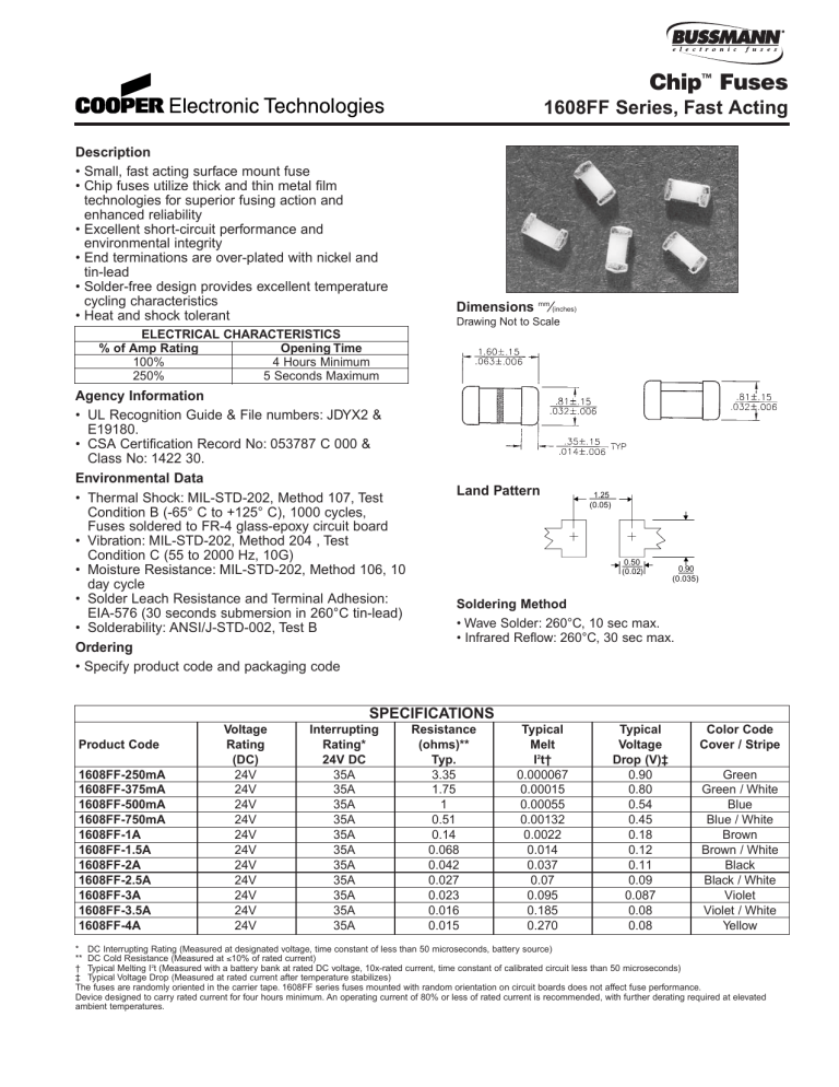
Dimensions mm ⁄
(inches)
Drawing Not to Scale
Land Pattern
1.25
(0.05)
0.50
(0.02)
Soldering Method
• Wave Solder: 260°C, 10 sec max.
• Infrared Reflow: 260°C, 30 sec max.
0.90
(0.035)
Product Code
1608FF-250mA
1608FF-375mA
1608FF-500mA
1608FF-750mA
1608FF-1A
1608FF-1.5A
1608FF-2A
1608FF-2.5A
1608FF-3A
1608FF-3.5A
1608FF-4A
Voltage
Rating
(DC)
24V
24V
24V
24V
24V
24V
24V
24V
24V
24V
24V
Interrupting
Rating*
24V DC
35A
35A
35A
35A
35A
35A
35A
35A
35A
35A
35A
SPECIFICATIONS
Resistance
(ohms)**
Typ.
3.35
1.75
1
0.51
0.14
0.068
0.042
0.027
0.023
0.016
0.015
Typical
Melt
I 2 t†
0.000067
0.00015
0.00055
0.00132
0.0022
0.014
0.037
0.07
0.095
0.185
0.270
Typical
Voltage
Drop (V)‡
0.90
0.80
0.54
0.45
0.18
0.12
0.11
0.09
0.087
0.08
0.08
Color Code
Cover / Stripe
Green
Green / White
Blue
Blue / White
Brown
Brown / White
Black
Black / White
Violet
Violet / White
Yellow
* DC Interrupting Rating (Measured at designated voltage, time constant of less than 50 microseconds, battery source)
** DC Cold Resistance (Measured at ≤ 10% of rated current)
† Typical Melting I 2 t (Measured with a battery bank at rated DC voltage, 10x-rated current, time constant of calibrated circuit less than 50 microseconds)
‡ Typical Voltage Drop (Measured at rated current after temperature stabilizes)
The fuses are randomly oriented in the carrier tape. 1608FF series fuses mounted with random orientation on circuit boards does not affect fuse performance.
Device designed to carry rated current for four hours minimum. An operating current of 80% or less of rated current is recommended, with further derating required at elevated ambient temperatures.
TIME CURRENT CURVE
Chip
™
Fuses
1608FF Series, Fast Acting
Packaging Code
SP
TR
PACKAGING CODE
Description
50 piece sample pack
3,000 pieces of fuses on 8mm tape-and-reel on a 7 inch (178mm) reel per EIA Standard 481
OC-2532 Rev. E 4/02
© Cooper Electronic
Technologies 2002
Visit us on the Web at www.cooperET.com
3601 Quantum Boulevard Boynton Beach, Florida 33426-8638
Tel: +1-561-752-5000 Toll Free: +1-888-414-2645 Fax: +1-561-742-1178
This bulletin is intended to present product design solutions and technical information that will help the end user with design applications. Cooper
Electronic Technologies reserves the right, without notice, to change design or construction of any products and to discontinue or limit distribution of any products. Cooper Electronic Technologies also reserves the right to change or update, without notice, any technical information contained in this bulletin. Once a product has been selected, it should be tested by the user in all possible applications.
