1847151 Pres Sen Bridge Unit
advertisement

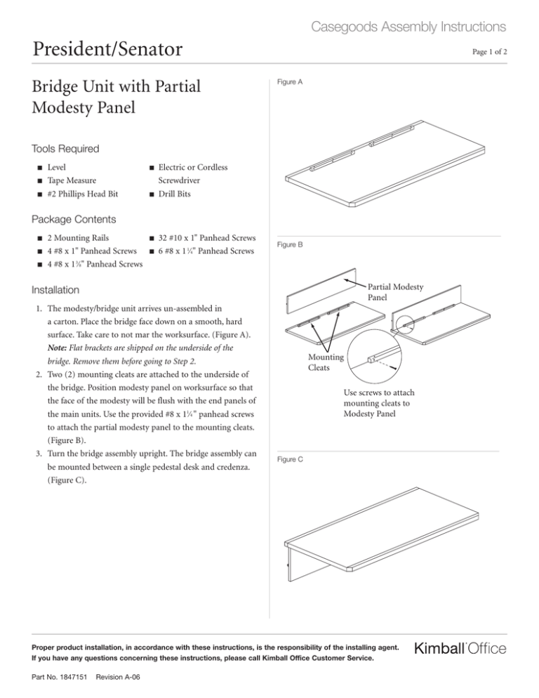
Casegoods Assembly Instructions President/Senator Bridge Unit with Partial Modesty Panel Page 1 of 2 Figure A Tools Required ■ ■ ■ Level Tape Measure #2 Phillips Head Bit ■ ■ Electric or Cordless Screwdriver Drill Bits Package Contents ■ ■ ■ 2 Mounting Rails 4 #8 x 1" Panhead Screws 4 #8 x 1 3⁄8" Panhead Screws ■ ■ 32 #10 x 1" Panhead Screws 6 #8 x 1 1⁄4" Panhead Screws Figure B Partial Modesty Panel Installation 1. The modesty/bridge unit arrives un-assembled in a carton. Place the bridge face down on a smooth, hard surface. Take care to not mar the worksurface. (Figure A). Note: Flat brackets are shipped on the underside of the bridge. Remove them before going to Step 2. 2. Two (2) mounting cleats are attached to the underside of the bridge. Position modesty panel on worksurface so that the face of the modesty will be flush with the end panels of the main units. Use the provided #8 x 11⁄4 " panhead screws to attach the partial modesty panel to the mounting cleats. (Figure B). 3. Turn the bridge assembly upright. The bridge assembly can be mounted between a single pedestal desk and credenza. (Figure C). Mounting Cleats Use screws to attach mounting cleats to Modesty Panel Figure C Proper product installation, in accordance with these instructions, is the responsibility of the installing agent. If you have any questions concerning these instructions, please call Kimball Office Customer Service. Part No. 1847151 Revision A-06 Casegoods Assembly Instructions President/Senator Installation (continued) Page 2 of 2 Figure E Main unit Align Flush with no gaps Bridge/Modesty Use #8 x 1" screws to attach thinner portion Thicker portion of rail attaches to Modesty Panel Figure F Modesty Panel Use #8 x 1 ⁄ " screws to attach thicker portion Mounting Rail T 800.482.1818 Desk/Credenza End Panel Figure G Figure D Flush with no gaps 4" 19" Proper product installation, in accordance with these instructions, is the responsibility of the installing agent. If you have any questions concerning these instructions, please call Kimball Office Customer Service. Part No. 1847151 8 Revision A-06 F 812.482.8300 3 Flush with no gaps Printed in U.S.A. © 2004 Kimball International, Inc. 4. Position the main units in the desired locations. Leave enough space between the two units to allow for placement of the bridge. Level main units. Install the flat brackets to the undersides of the main units using the provided #10 x 1" panhead screws. Locate the flat brackets using the dimensions shown. Center the brackets with the edges of the unit worksurfaces. (Figure D). 5. Align the bridge worksurface to the main units. Position the tops so the outer edges of the main units and bridge worksurface are tight against each other with no gaps. Attach the bridge worksurface to the flat brackets with the provided #10 x 1" panhead screws. (Figure E). 6. The vertical mounting rails have a step in them to account for differences in thickness between the main unit end panels and the modesty panel. Position each mounting rail where the modesty meets an end panel. Make sure the thicker portion of the mounting rail is against the modesty panel. Make sure the rail is flush against all surfaces and corners with no gaps. Attach the thin portion of each rail with two (2) of the provided #8 x 1" panhead screws. Attach the thick portion of each rail with two (2) of the provided #8 x 1 3⁄8" panhead screws. (Figure F). 7. Re-level all units. Align all margins vertically between the modesty panel and desk/credenza end panels. Eliminate all gaps. (Figure G).


