High voltage measurements Characterization of NiMH batteries with
advertisement

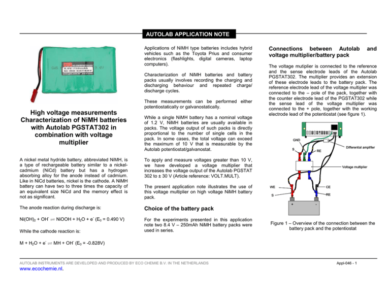
AUTOLAB APPLICATION NOTE Applications of NiMH type batteries includes hybrid vehicles such as the Toyota Prius and consumer electronics (flashlights, digital cameras, laptop computers). Characterization of NiMH batteries and battery packs usually involves recording the charging and discharging behaviour and repeated charge/ discharge cycles. These measurements can be performed either potentiostatically or galvanostatically. High voltage measurements Characterization of NiMH batteries with Autolab PGSTAT302 in combination with voltage multiplier While a single NiMH battery has a nominal voltage of 1.2 V, NiMH batteries are usually available in packs. The voltage output of such packs is directly proportional to the number of single cells in the pack. In some cases, the total voltage can exceed the maximum of 10 V that is measurable by the Autolab potentiostat/galvanostat. A nickel metal hydride battery, abbreviated NiMH, is a type of rechargeable battery similar to a nickelcadmium (NiCd) battery but has a hydrogen absorbing alloy for the anode instead of cadmium. Like in NiCd batteries, nickel is the cathode. A NiMH battery can have two to three times the capacity of an equivalent size NiCd and the memory effect is not as significant. The present application note illustrates the use of this voltage multiplier on high voltage NiMH battery pack. The anode reaction during discharge is: Choice of the battery pack Ni(OH)2 + OH- ⇌ NiOOH + H2O + e- (E0 = 0.490 V) For the experiments presented in this application note two 8.4 V – 250mAh NiMH battery packs were used in series. While the cathode reaction is: - Connections between Autolab voltage multiplier/battery pack The voltage mutiplier is connected to the reference and the sense electrode leads of the Autolab PGSTAT302. The multiplier provides an extension of these electrode leads to the battery pack. The reference electrode lead of the voltage multipler was connected to the – pole of the pack, together with the counter electrode lead of the PGSTAT302 while the sense lead of the voltage multiplier was connected to the + pole, together with the working electrode lead of the potentiostat (see figure 1). GND Differential amplifier S RE To apply and measure voltages greater than 10 V, we have developed a voltage multiplier that increases the voltage output of the Autolab PGSTAT 302 to ± 30 V (Article reference: VOLT.MULT). Voltage multiplier WE CE S RE + - Figure 1 – Overview of the connection between the battery pack and the potentiostat - M + H2O + e ⇌ MH + OH (E0 = -0.828V) AUTOLAB INSTRUMENTS ARE DEVELOPED AND PRODUCED BY ECO CHEMIE B.V. IN THE NETHERLANDS www.ecochemie.nl. and Appl-046 - 1 AUTOLAB APPLICATION NOTE Experimental conditions (DC measurements) Before the experiments were carried out, the battery pack was charged with a current of 100 mA supplied by the potentiostat. The charging time was about 600 seconds. voltage (OCP) was 19 V, while the final voltage, at – 150 mA discharge current was 17.7 V. This potential profile has the typical shape of the discharge profile of a NiMH battery. an applied potential of 18.3 V. The discharge voltage was 17.3 V. Three series of experiments were performed in order to illustrate the use of the voltage multiplier. In the first series of experiments, the battery pack was charged during 60 seconds with a current of 100 mA. Shortly thereafter, the batery pack was discharged using a discharge current sweep between 0 A and -150 mA while monitoring the ouput voltage of the pack. Different discharge currents were used. The second series of experiments consisted in a repetition of constant charge (100 mA) and discharge current (-100 mA) during which the output voltage was recorded. In the third set of experiments, the battery pack was continuously charged and discharge by applying positive and negative overvoltages relative to the open circuit potential (OCP +/- 0.5 V). The results presented in this application note were obtained with the Nova software package. The measurements are also possible in GPES. Experimental results Figure 2 shows the output voltage response of the battery pack during the discharge sweep. The initial Figure 2 – Discharge current sweep from 0 mA to – 150 mA at 1 mA/s Figure 3 shows the chrono charge/discharge profile of the battery pack after a series of 10 cycles. Both charging and discharging currents were 100 mA. The output voltage of the battery reaches a maximum value of 18.6 V in the last charging step and a mimimum output voltage of 17.7 V during the first discharge step. Figure 4 shows the current response during repeated potentiostatic charging and discharging of the battery. The charging voltage was +0.5 V, applied with respect to the OCP, which resulted in AUTOLAB INSTRUMENTS ARE DEVELOPED AND PRODUCED BY ECO CHEMIE B.V. IN THE NETHERLANDS www.ecochemie.nl. Figure 3 – Charge/discharge potential profile during time (charging current: 100 mA, blue line/discharging current: -100 mA, red line) Appl-046 - 2 AUTOLAB APPLICATION NOTE blue line corresponds to the change of total impedance. (to apply potentials higher than 10 V). The voltage multiplier can be used with all the available measurement techniques, AC or DC. Figure 4 – Charge/discharge current profile during time (charging potential: 18.3 V/discharging potential: 17.3 V) Experimental conditions (AC measurements) The voltage multiplier can also be used to perform impedance measurements. To illustrate this, an frequency scan with a DC voltage of 16.8 V and an AC voltage of 0.1 V was carried out, starting at a frequency of 10 kHz, down to 0.1 Hz. Experimental results Figure 5 shows the recorded impedance spectrum for the NiMH battery pack, as a Bode plot. The red line corresponds to the phase angle change and the Figure 5 – Bode plot recorded at a DC voltage of 16.8 V with an AC amplitude of 0.1 V (red line: phase angle, blue line: total impedance) Conclusions This application note has illustrated the use of the voltage multiplier designed for the Autolab PGSTAT302. This device allows to increase the applied potential range of the potentiostat up to a maximum value equal to its compliance voltage (30V). This is convenient in order to study energy storage devices that are able to deliver potentials higher than the 10 V limit. The voltage multiplier can be used both in galvanostatic mode (to measure voltage higher than 10 V) or in potentiostatic mode AUTOLAB INSTRUMENTS ARE DEVELOPED AND PRODUCED BY ECO CHEMIE B.V. IN THE NETHERLANDS www.ecochemie.nl. Appl-046 - 3


