Interior Lighting Systems (NEW! 9/27/07)
advertisement
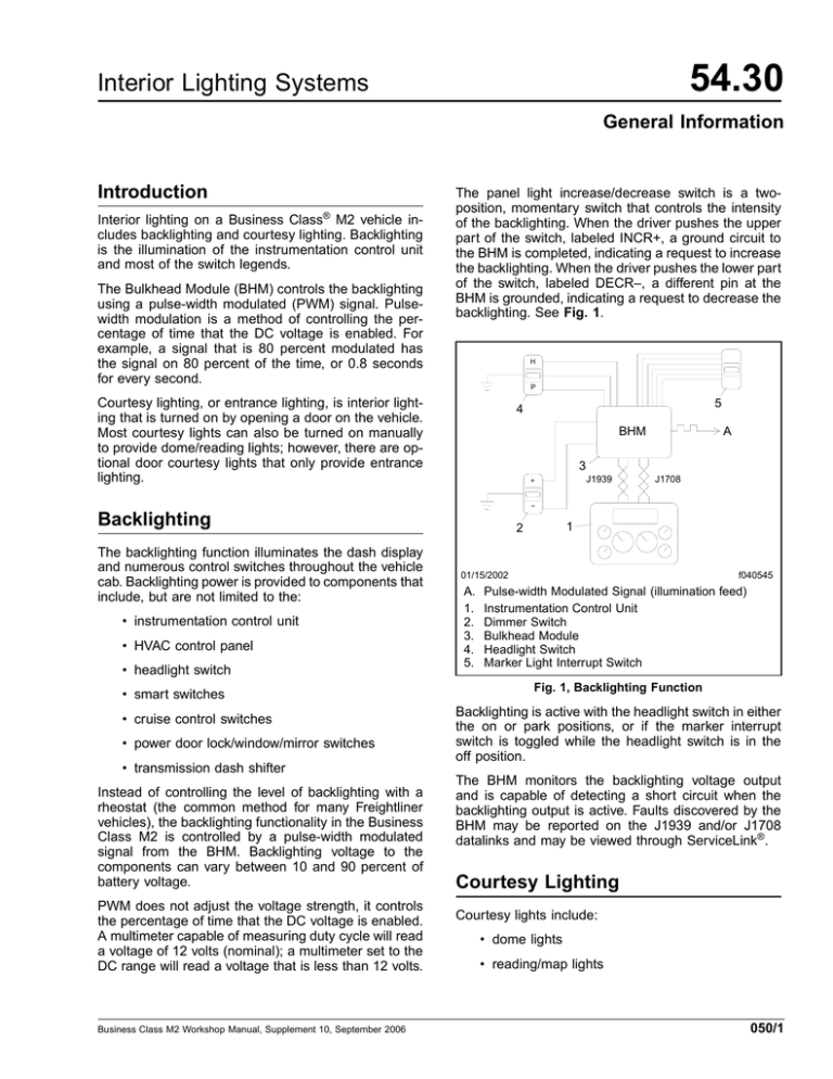
54.30 Interior Lighting Systems General Information Introduction Interior lighting on a Business Class® M2 vehicle includes backlighting and courtesy lighting. Backlighting is the illumination of the instrumentation control unit and most of the switch legends. The Bulkhead Module (BHM) controls the backlighting using a pulse-width modulated (PWM) signal. Pulsewidth modulation is a method of controlling the percentage of time that the DC voltage is enabled. For example, a signal that is 80 percent modulated has the signal on 80 percent of the time, or 0.8 seconds for every second. The panel light increase/decrease switch is a twoposition, momentary switch that controls the intensity of the backlighting. When the driver pushes the upper part of the switch, labeled INCR+, a ground circuit to the BHM is completed, indicating a request to increase the backlighting. When the driver pushes the lower part of the switch, labeled DECR–, a different pin at the BHM is grounded, indicating a request to decrease the backlighting. See Fig. 1. H P Courtesy lighting, or entrance lighting, is interior lighting that is turned on by opening a door on the vehicle. Most courtesy lights can also be turned on manually to provide dome/reading lights; however, there are optional door courtesy lights that only provide entrance lighting. 5 4 A BHM 3 J1939 + J1708 − Backlighting The backlighting function illuminates the dash display and numerous control switches throughout the vehicle cab. Backlighting power is provided to components that include, but are not limited to the: • instrumentation control unit • HVAC control panel • headlight switch • smart switches • cruise control switches • power door lock/window/mirror switches • transmission dash shifter Instead of controlling the level of backlighting with a rheostat (the common method for many Freightliner vehicles), the backlighting functionality in the Business Class M2 is controlled by a pulse-width modulated signal from the BHM. Backlighting voltage to the components can vary between 10 and 90 percent of battery voltage. PWM does not adjust the voltage strength, it controls the percentage of time that the DC voltage is enabled. A multimeter capable of measuring duty cycle will read a voltage of 12 volts (nominal); a multimeter set to the DC range will read a voltage that is less than 12 volts. Business Class M2 Workshop Manual, Supplement 10, September 2006 1 2 f040545 01/15/2002 A. 1. 2. 3. 4. 5. Pulse-width Modulated Signal (illumination feed) Instrumentation Control Unit Dimmer Switch Bulkhead Module Headlight Switch Marker Light Interrupt Switch Fig. 1, Backlighting Function Backlighting is active with the headlight switch in either the on or park positions, or if the marker interrupt switch is toggled while the headlight switch is in the off position. The BHM monitors the backlighting voltage output and is capable of detecting a short circuit when the backlighting output is active. Faults discovered by the BHM may be reported on the J1939 and/or J1708 datalinks and may be viewed through ServiceLink®. Courtesy Lighting Courtesy lights include: • dome lights • reading/map lights 050/1 54.30 Interior Lighting Systems General Information • door entrance lights • overhead console lights The number and location of the courtesy lights varies depending on cab configuration and vehicle options. Courtesy lighting variations range from day cabs with one-switch activation (driver door) of a dome light assembly, to crew cabs with four-switch activation of the dome lights, reading lights, and optional door courtesy lights. The BHM is capable of detecting shorted circuits in the courtesy lights wiring. Faults discovered by the BHM may be reported on the J1939 and/or J1708 datalinks and may be viewed through ServiceLink. Dome Lights Dome lights are installed on all cabs. The basic dome light has a clear lens and is installed above the rear window. On cabs with an overhead console, there is an optional lighting assembly that contains two dome lights and two reading lights. Additional dome lights located in the headliner are available on crew cabs and extended cabs. A dome light can be turned on by opening a door or pressing the switch on the dome light. There are two separate power circuits coming from the BHM to the dome light assembly. One circuit from pin A of BHM connector B5 has power at all times and is used to turn the light on when the driver presses the switch on the dome light. The other circuit from pin B of BHM connector B5 is powered when a door is opened. See Fig. 2. The number and location of door pin switches that activate the dome light(s) vary with cab configuration and vehicle options. On day cabs and extended cabs, the driver door switch is standard and the passenger side door switch is optional. On crew cabs, all four door switches are standard. Reading/Map Lights Reading lights are clear lights that are available with: • The optional lighting assembly on a cab with an overhead console; • A crew cab that has optional dome/reading light assemblies. In the overhead console lighting assembly, the reading lights are located on either side of the overhead console next to the dome lights. The reading lights in this assembly are nonreplaceable light-emitting diode (LED) modules. Map lights are red lights that are available instead of the clear reading lights in the overhead console. Door Entrance Lights Door entrance lights are located on the inner door panels. These lights are only activated when a door is opened and can not be turned on manually. The door entrance lights provide additional interior lighting when getting in and out of the vehicle. Most cab configurations utilize the dome light output at pin B of BHM connector B5 to activate the door courtesy lights; however, there are a few crew cab configurations where the Chassis Module (CHM) is used to activate the door entrance lights to remove some of the current load from the BHM output. For these configurations, the BHM sends datalink messages to the CHM requesting courtesy light activation. The CHM output at pin C of CHM connector C3 powers the door entrance lights. 5 6 B 7 4 8 BHM 3 A J1708 2 J1939 1 f040548 01/15/2002 A. 1. 2. 3. 4. 5. 6. 7. 8. Passenger Side B. Driver Side Instrumentation Control Unit Rear Door Switch Front Door Switch Rear Door Switch Front Door Switch Bulkhead Module Dome Light Switch Dome Lamp Bulb Fig. 2, Dome Light Function 050/2 Business Class M2 Workshop Manual, Supplement 10, September 2006 54.30 Interior Lighting Systems General Information Current Capacity For cab configurations where the BHM powers many courtesy lights, it is necessary to be aware that exceeding the current capacity of a BHM output results in the BHM shutdown of that output. If adding additional interior lights to a vehicle, do not exceed the current capacity of control module output. See Table 1 for identification of possible courtesy light outputs and the current capacity of those outputs. Courtesy Light Outputs Function Current Capacity Module Pin Connector BHM A B5 Dome lights battery power 6.7A* BHM B B5 Dome lights and optional door courtesy lights switched power 6.7A CHM C C3 Door courtesy lights (unused fog light output) 6.7A† * Pins B5-A and B7-A12 (smart switch battery power) are fed from the same BHM circuit board trace. The maximum combined current capacity for both pins is 6.7A. † Pins C3-C and C3-D (optional fog light) are fed from the same CHM circuit board trace. The maximum combined current capacity for both pins is 6.7A. Table 1, Courtesy Light Outputs Business Class M2 Workshop Manual, Supplement 10, September 2006 050/3 54.30 Interior Lighting Systems Interior Lights Replacement Cab Rear Dome Light Bulb Replacement Overhead Console Map/Reading Light Assembly Bulb Replacement 1. Remove the lens using a flat-blade screwdriver to release the two tabs on the bottom of the lens. Then gently pry the lens from the bottom of the housing. NOTE: The bulbs are replaceable in the inner larger lights only. The smaller lights use nonreplaceable LEDs. 2. Remove the two bulbs from the lock clips by pulling them straight out. See Fig. 1. 1. Using a flat-blade screwdriver, release the tab by pushing on the edge of the lens that is indented. Then gently pry the lens from the housing. 3. Press new bulbs into the lock clips. 4. Insert the two tabs on the lens into the slots in the top of the housing, then push the bottom of the lens into place, locking the tabs. Cab Rear Dome Light Assembly Replacement 1. Remove the lens using a flat-blade screwdriver to release the two tabs on the bottom of the lens. Then gently pry the lens from the bottom of the housing. 2. Insert the screwdriver into the lower slots in the housing to release the two spring clips, then remove the assembly from the headliner. 3. Disconnect the electrical connector. 4. Connect the electrical connector of the new assembly. 5. Align the tabs on the top edge of the new assembly and press the lower edge of the assembly into place until the locking tabs click into place. 2. Remove the bulb from the lock clip by pulling it straight out. 3. Press a new bulb into the lock clip. 4. Insert the tab on the lens into the slots in the housing, then push the lens into place, locking the tabs. Overhead Console Map/Reading Light Assembly Replacement 1. Remove the three Torx® capscrews that hold the center overhead panel in place. See Fig. 2. 2. Lower the assembly and disconnect the connector to the light assembly. 3. Remove the four capscrews that attach the light assembly to the panel, and remove the light assembly. 4. Using capscrews, install a new light assembly on the panel. 5. Connect the connector to the light assembly. 6. Using capscrews, install the center overhead panel. 1 07/17/2003 f544339 1. Bulb Fig. 1, Cab Rear Dome Light Business Class M2 Workshop Manual, Supplement 10, September 2006 100/1 54.30 Interior Lighting Systems Interior Lights Replacement 1 3 2 3 3 07/18/2003 f544338 1. Center Overhead Panel 2. Reading Light With Replaceable Bulb 3. Torx Capscrew Fig. 2, Overhead Panel With Map/Reading Lights 100/2 Business Class M2 Workshop Manual, Supplement 10, September 2006 54.30 Interior Lighting Systems Troubleshooting IMPORTANT: ServiceLink® is the diagnostic tool for troubleshooting the M2 electrical system. For specific circuit and pin information on how the vehicle is wired, go to the Configuration screen in ServiceLink and select the specific function in which you are interested. To troubleshoot specific inputs and outputs of this system, go to the Templates screen in ServiceLink and select the template for the function in which you are interested. the BHM determine whether or not a fault code is broadcast. Therefore, even if the BHM detects a fault, a fault code may not be transmitted. If the BHM is programmed to transmit fault codes, they can be viewed through ServiceLink. Fault messages may be transmitted on the J1939 and/or the J1708 datalinks until both the headlight switch and the marker interrupt switch are turned off. Dome Light Fault Conditions Backlighting See Table 3 for the dome light conditions that will create a fault. The reference parameters that program the BHM determine whether or not a fault code is broadcast. Therefore, even if the BHM detects a fault, a fault code may not be transmitted. If the BHM is programmed to transmit fault codes, they can be viewed through ServiceLink. Fault messages may be transmitted on the J1939 and/or the J1708 datalinks until the ignition switch is turned off. Input and Output Conditions See Table 1 for the Bulkhead Module (BHM) responses to the backlighting input/output conditions. Fault Conditions See Table 2 for the backlighting conditions that will create a fault. The reference parameters that program Backlighting Input/Output Conditions Inputs to BHM Outputs from BHM Headlight Switch Marker Interrupt Switch Backlight Status Illumination Percent Battery Voltage Output On/Park Off On Dependent on dimmer switch position (range dim to bright). Dependent on dimmer switch position (range 10 to 90%). Off On On Bright 100% On/Park On Off Off 0% Off Off Off Off 0% Table 1, Backlighting Input/Output Conditions Backlighting Fault Conditions Failed Component or Circuit Description of Fault Action Taken by BHM Backlight dimmer switch BHM sees panel light increase and panel light decrease simultaneously. BHM may transmit a J1939 and/or a J1708 fault message. Headlight switch Headlight switch is in error. BHM will assume the headlight switch is on. Marker interrupt switch Marker interrupt switch is in error. BHM will assume the marker interrupt switch is off and may transmit a fault message on the J1939 and/or J1708 datalinks. Backlighting power output Backlighting power wiring is shorted. BHM may transmit a J1939 and/or a J1708 fault message. Table 2, Backlighting Fault Conditions Business Class M2 Workshop Manual, Supplement 10, September 2006 300/1 54.30 Interior Lighting Systems Troubleshooting Dome Light Fault Conditions Description of Fault Action Taken by BHM Dome light power (hot at all times) wiring is shorted. BHM may transmit a J1939 and/or a J1708 fault message. Dome light switched (hot with door switch closed) wiring is shorted. BHM may transmit a J1939 and/or a J1708 fault message. Table 3, Dome Light Fault Conditions 300/2 Business Class M2 Workshop Manual, Supplement 10, September 2006 Interior Lighting Systems 54.30 Specifications Wiring Diagrams IMPORTANT: The following wiring diagrams show typical interior lighting configurations available for a Business Class® M2 vehicle. The circuit details shown may not correspond to every vehicle. ServiceLink® is the diagnostic tool for troubleshooting the M2 electrical system. For specific circuit and pin information on how the vehicle is wired, go to the Configuration screen in ServiceLink and select the specific function in which you are interested. To troubleshoot specific inputs and outputs of this system, go to the Templates screen in ServiceLink and select the template for the function in which you are interested. • An overhead console, four dome lights, and optional front door entrance lights. See Fig. 7. • An overhead console, four dome lights, and CHM-controlled door entrance lights. See Fig. 8. Backlighting See Fig. 1 and Fig. 2 for backlighting wiring diagrams showing dimmer controls and instrument illumination. Courtesy Lights The number and location of courtesy lights are dependent on the vehicle configuration and vehicle options. Day Cabs and Extended Cabs See Fig. 3 for a wiring diagram of the courtesy lights for a cab with a single rear dome light. See Fig. 4 for a wiring diagram of the courtesy lights for a cab with the optional lighting assembly in the overhead console. Crew Cabs Courtesy light door switches are standard on a crew cab. The courtesy lights are activated by opening any of the four vehicle doors. See Fig. 5 for a wiring diagram of the door switches. There are many interior lighting configurations available for crew cab vehicles. The Bulkhead Module (BHM) outputs that drive the interior lights have a limited load capacity. As supplied interior lighting increases, sometimes it is necessary to feed the door courtesy lights from an unused Chassis Module (CHM) output to prevent BHM output overload. Typical examples of crew cab courtesy light configurations include: • Two dome lights and optional door entrance lights. See Fig. 6. Business Class M2 Workshop Manual, Supplement 10, September 2006 400/1 54.30 Interior Lighting Systems Specifications BR 11 9 BK Smart Switches Smart switch backlighting A1 B7 BR 29A BR 11 9 BK BR 11 9 BK BR 11 9 BK BR 11 9 BK BK GNDE BK GNDE BK−W 2B Battery Ground Backlighting increase B5 BR 29C B6 B6 BR 29 H B5 BR 29C BR 3 29 BR 1 DIM + OFF Backlighting decrease Backlighting PWM output DIM − 29A 29A BR 9 GND BK 7 Bulkhead Module BK Backlight feed A1 C1 BR Ground D3 C2 BK−W GNDE Left Interior Frontwall Ground 29A ILLUM Dimmer Switch Battery Ground 29A BK BK 8 29A BR 10 BR Instrumentation Control Unit GND Backlight feed Ground A2 BR 29A B8 BK GND BK Headlight Switch Left Interior Frontwall Ground HVAC Control Head MBE900 BK GND 12 10 BR 29A MBE900 Caterpillar BK 29A 6 29A BR GND BK Left Interior Frontwall Ground Caterpillar BR 10 BK 8 Cruise Set/Resume Switch 29A BR 10 GND BK 9 Cruise Set/Resume Switch A BR Cruise On/Off Switch 11 29A GND Illumination Splice Pack f544786 05/18/2006 Fig. 1, Backlighting Dimmer Controls 400/2 Business Class M2 Workshop Manual, Supplement 10, September 2006 54.30 Interior Lighting Systems Specifications A BHM pulse−width modulated backlighting output F L BR A1 29A BR 29A K G BR 29A BR 29A BR E BR 29A 29A J BR 29A H D BR 29A BR C BR 29A 29A B BR Not Used 29A M Illumination Splice Pack Dual Mirror Switch Door Lock Switches 29A 10 6 ATC Switch BK BK GND GND GND BK 8 BK Right Power Window Switch GND Left Power Window Switch GND BK GND 10 BR 29A GND GND BK 8 10 BR 29A BR 10 8 Overdrive Switch BK Fan Clutch Switch BK BK GND 6 A B BK Transmission Dash Shifter GND 9 Engine Check Switch GND BK 10 10 BR 29A BK A4 Exhaust Brake Switch GND Smart Shift Display Left Interior Frontwall Ground 05/18/2006 f544787 Fig. 2, Backlighting Business Class M2 Workshop Manual, Supplement 10, September 2006 400/3 54.30 Interior Lighting Systems Specifications 108C A PRP−W BK B 108C B A PRP−W GND B Left Door Entrance Light (if equipped) Battery Ground BK Left Interior Frontwall Ground F BK−W GND BK Dome Light BK Right Door Entrance Light (if equipped) Left Door Courtesy Switch GND A A C A6 PRP−W 109C B6 Right Door Courtesy Switch 108C PRP−W 108D A7 PRP−W 108C C Bulkhead Module A PRP−W 41 B5 GNDE BK−W Passenger door open PRP−W A Driver door open PRP−W 108D C Dome battery power B GNDE BK−W Dome switched power Cab Ground Splice Pack (SP1) 05/18/2006 f544788 Fig. 3, Single Rear Dome Light 400/4 Business Class M2 Workshop Manual, Supplement 10, September 2006 54.30 Interior Lighting Systems Specifications A PRP−W 41 B5 A7 PRP−W 108C Left Door Courtesy Switch GND BK C BK GND Right Overhead Console Lights Left Interior Frontwall Ground J C BK Left Overhead Console Lights G GND B BK GND F Battery Ground Center Dome Light B BK Door Entrance Lights (if equipped) GND GNDE BK−W Reading Light LED Module L BK C B R Reading Light LED Module BK−W GNDE BK−W C Right Door Courtesy Switch A PRP−W A PRP−W Dome 108C PRP−W 108D A Dome 108C PRP−W 41 PRP−W 41 A B PRP−W 108D PRP−W 108C A C PRP−W 109C A Bulkhead Module PRP−W 108D A6 PRP−W 109C B6 A Passenger door open PRP−W 108C PRP−W 41 Driver door open PRP−W 108D B Dome battery power B PRP−W 108D Dome switched power Cab Ground Splice Pack (SP1) 05/22/2006 f544789 Fig. 4, Overhead Console Business Class M2 Workshop Manual, Supplement 10, September 2006 400/5 54.30 Interior Lighting Systems Specifications 109C PRP−W 108C 1 2 Left Rear Door Courtesy Switch GNDE BK−W 1 2 GNDE BK−W Right Front Door Courtesy Switch Right Rear Door Courtesy Switch C BK−W C Left Front Door Courtesy Switch BK−W GNDE BK−W C A PRP−W 108C PRP−W 109C A7 PRP−W 108C B6 A Bulkhead Module PRP−W GNDE BK−W Left side door open A6 PRP−W 109C PRP−W 108C Right side door open Battery Ground 06/02/2006 Dash Ground Splice Pack (SP6) f544790 Fig. 5, Crew Cab Door Switches 400/6 Business Class M2 Workshop Manual, Supplement 10, September 2006 54.30 Interior Lighting Systems Specifications PRP−W 108D PRP−W 108C 108C B Right Front Door Entrance Light GND BK A PRP−W B Left Front Door Entrance Light GND BK A PRP−W 108C 108C A PRP−W B PRP−W 108D C BK BK PRP−W 41 A B BK Right Rear Door Entrance Light Rear Center Dome Light Left Interior Frontwall Ground C D BK GND Front Center Dome Light K F GND BK B GND Left Rear Door Entrance Light GND PRP−W 108D C B PRP−W 41 A Bulkhead Module 108C A PRP−W 41 B5 A PRP−W Dome battery power B PRP−W 108D Dome switched power Cab Ground Splice Pack 05/18/2006 f544791 Fig. 6, Two Dome Lights Business Class M2 Workshop Manual, Supplement 10, September 2006 400/7 54.30 Interior Lighting Systems Specifications Dome battery power B PRP−W 108D 108C PRP−W A PRP−W 108C PRP−W 108D Dome switched power A PRP−W 41 B5 Bulkhead Module B BK GND BK Left Interior Frontwall Ground Left Front Door Entrance Light (if equipped) 108C PRP−W A B BK GND PRP−W 41 PRP−W 108D A PRP−W 108D A B PRP−W 41 B PRP−W 108D C GND M BK C GND K BK C GND L BK C Center Rear Dome/ Reading Light GND Left Rear Dome/ Reading Light J Right Overhead Console Lights GND BK C Read G BK B BK Dome GND Left Overhead Console Lights Read Dome Reading Light LED Module F Front Console Dome Light A Dome Read Reading Light LED Module PRP−W 41 PRP−W 108D A Dome Dome B PRP−W 41 PRP−W 108D A B PRP−W 41 PRP−W 41 A B PRP−W 108D C Right Front Door Entrance Light (if equipped) Right Rear Dome/ Reading Light Cab Ground Splice Pack (SP1) 05/22/2006 f544792 Fig. 7, Six Dome Lights with Optional Front Entrance Lights 400/8 Business Class M2 Workshop Manual, Supplement 10, September 2006 54.30 Interior Lighting Systems Specifications 1939+ 1939− Chassis Module C PRP−W 108C C3 G Y 1939− Dome switched power Dome battery power 108C PRP−W A B 1939+ B Y 108C PRP−W A BK GND Right Front Door Entrance Light BK GND Left Rear Door Entrance Light B 108D PRP−W A 1939+ J DKG 1939− B2 B B B 108D PRP−W A BK GND Left Front Door Entrance Light R DKG 1939− C4 Datalink 1939+ 108D PRP−W BK GND Right Rear Door Entrance Light BK Door courtesy lights 108C PRP−W Left Interior Frontwall Ground PRP−W 108D A PRP−W 41 B5 Read Read PRP−W 41 PRP−W 108D A PRP−W 108D A B PRP−W 41 PRP−W 108D B Dome Read Cab Ground Splice Pack (SP1) Dome BK Right Rear Dome/ Reading Light C GND C BK Center Rear Dome/ Reading Light M GND C GND K BK C BK GND Left Rear Dome/ Reading Light L C BK Right Overhead Console Lights GND Left Overhead Console Lights J C BK G GND B BK GND F 05/22/2006 Dome Reading Light LED Module Reading Light LED Module Front Center Dome Light A Dome PRP−W 41 PRP−W 108D A Dome B PRP−W 41 PRP−W 108D A B PRP−W 41 PRP−W 41 A B PRP−W 108D C Bulkhead Module f544793 Fig. 8, Six Dome Lights with Four Entrance Lights Business Class M2 Workshop Manual, Supplement 10, September 2006 400/9

