Solid State Relay Parallel and DC Operation
advertisement

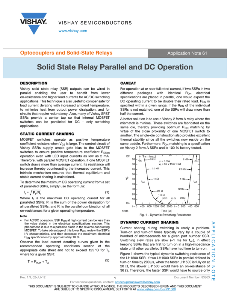
VISHAY SEMICONDUCTORS www.vishay.com Optocouplers and Solid-State Relays Application Note 61 Solid State Relay Parallel and DC Operation DESCRIPTION CAVEAT Vishay solid state relay (SSR) outputs can be wired in parallel enabling the user to benefit from lower on-resistance and higher load currents for AC/DC switching applications. This technique is also useful to compensate for load current derating with increased ambient temperature, to minimize heat from output power dissipation, and for circuits that require redundancy. Also, many of Vishay SPST SSRs provide a center tap so that internal MOSFET switches can be paralleled for DC - only switching applications. For operation at or near full rated current, if two SSRs in two different packages with identical RON electrical specifications are placed in parallel, one would expect the DC operating current to be double their rated load. RON is specified within a given range; if the RON of the individual SSRs is not matched, one of the SSRs will draw more than half the current. MOSFET switches operate as positive temperature coefficient resistors when VGS is large. The control circuit of Vishay SSRs supply ample gate bias to the MOSFET switches to ensure positive temperature coefficient RDSon operation even with LED input currents as low as 2 mA. Therefore, with parallel MOSFET operation, if one MOSFET switch draws more than average current, its resistance will increase thereby counteracting the increased current. This intrinsic mechanism ensures that thermal equilibrium and stable current sharing is maintained. Off 90 70 Pt /Rt Observe the load current derating curves given in the recommended operating conditions section of the appropriate data sheet and not to exceed 125 °C for Tj, where for a given SSR: Tj = PthJA + TA Rev. 1.3, 02-Jul-12 (2) IF = 5 mA VL = 50 V thru 1 kΩ 9 kΩ 2.3 kΩ 2.3 k Ω 1 kΩ 1 kΩ GΩ ton 30 429 Ω 429 Ω 20 112 Ω 52 Ω 10 toff 20 Ω 20 Ω On t=0 17345 400 800 1200 1600 2000 t = 0 200 400 600 Time (µs) Fig. 1 - Dynamic Switching Resistance DYNAMIC CURRENT SHARING Current sharing during switching is rarely a problem. Turn-on and turn-off times typically vary by a couple of hundred of microseconds for a given part number SSR. Switching slew rates are slow (~1 ms for t on), in effect keeping SSRs that are first to turn on in a high-impedance state until other paralleled SSRs have had time to turn on. Figure 1 shows the typical dynamic switching resistance of the LH1500 SSR. If two LH1500 SSRs in parallel differed in turn-on time by 200 μs, when the faster LH1500 is fully on at 20 , the slower LH1500 would have an on-resistance of 36 . Therefore, the faster SSR would have to source only Document Number: 83863 1 For technical questions, contact: optocoupleranswers@vishay.com THIS DOCUMENT IS SUBJECT TO CHANGE WITHOUT NOTICE. THE PRODUCTS DESCRIBED HEREIN AND THIS DOCUMENT ARE SUBJECT TO SPECIFIC DISCLAIMERS, SET FORTH AT www.vishay.com/doc?91000 APPLICATION NOTE Note • For AC/DC operation, SSR RON at high current can be less than the value stated in the electrical specifications section. This phenomena is due to a parasitic diode in the reverse conducting MOSFET. To take advantage of this lower RON, review the SSR’s I-V characteristics, and then decrease the maximum electrical RON specification by approximately 10 %. 50 40 (1) Where It is the maximum DC operating current for all paralleled SSRs; Pt is the sum of the power dissipation for all paralleled SSRs; and Rt is the parallel combination of all on-resistances for a given operating temperature. 19 k Ω 9 kΩ 60 To determine the maximum DC operating current from a set of paralleled SSRs, simply use the formula: It = GΩ 80 % STATIC CURRENT SHARING A better solution is to use a Vishay 2 form A relay where the mismatch is minimal. These switches are fabricated on the same die, thereby providing optimum R ON matching by virtue of the close proximity of one MOSFET switch to another. The single-die construction also provides excellent thermal stability since all the switches now reside on the same paddle. Furthermore, RON matching is a specification on Vishay 2 form A SSRs and is 100 % factory tested. Application Note 61 www.vishay.com Vishay Semiconductors Solid State Relay Parallel and DC Operation 64 % of the load current for 200 μs. If the slew rates were fast, the faster SSR would have to source 100 % of the load current for 200 μs. With different part number SSRs, turn-on time deltas can become more pronounced, and dissimilar turn-on times could momentarily subject the fastest SSR to the full load current of the overall circuit. If many relays are paralleled to obtain a high-current operation, this current could potentially damage the SSRs. Most Vishay form A SSRs employ integrated current-limiting circuitry that will protect the relay from high-current transient conditions. Dynamic current sharing can be ignored when current-limited SSRs are used. For SSRs without current limiting, be sure that the overall load current does not exceed the absolute maximum pulsed peak current specification of the respective SSRs. DC OPERATION APPLICATION NOTE Similarly, most of the 6 pin Vishay SSRs can be wired for DC only operation. In this configuration, pins 4 and 6 are usually tied together, thereby paralleling the two internal MOSFET switches. Pins 4 and 6 become the positive output of the SSR, and pin 5 becomes the negative output. Here too, the MOSFET switches reside on the same die and static and dynamic current sharing are not an issue. Rev. 1.3, 02-Jul-12 Document Number: 83863 2 For technical questions, contact: optocoupleranswers@vishay.com THIS DOCUMENT IS SUBJECT TO CHANGE WITHOUT NOTICE. THE PRODUCTS DESCRIBED HEREIN AND THIS DOCUMENT ARE SUBJECT TO SPECIFIC DISCLAIMERS, SET FORTH AT www.vishay.com/doc?91000


