online homework 10 solution
advertisement
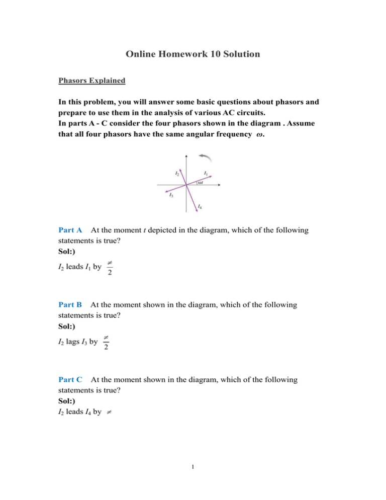
Online Homework 10 Solution Phasors Explained In this problem, you will answer some basic questions about phasors and prepare to use them in the analysis of various AC circuits. In parts A - C consider the four phasors shown in the diagram . Assume that all four phasors have the same angular frequency ω. Part A At the moment t depicted in the diagram, which of the following statements is true? Sol:) π I2 leads I1 by 2 Part B At the moment shown in the diagram, which of the following statements is true? Sol:) π I2 lags I3 by 2 Part C At the moment shown in the diagram, which of the following statements is true? Sol:) I2 leads I4 by π 1 Let us now consider some basic applications of phasors to AC circuits. • • For a resistor, the current and the voltage are always in phase. π For an inductor, the current lags the voltage by . • For a capacitor, the current leads the voltage by 2 π 2 . Part D Consider this diagram. Let us assume that it describes a series circuit containing a resistor, a capacitor, and an inductor. The current in the circuit has amplitude I, as indicated in the figure. Which of the following choices gives the correct respective labels of the voltages across the resistor, the capacitor, and the inductor? Sol:) I dQ = I 0 cos ωt ⇒ ∫ dQ = ∫ I 0 cos ωt ⇒ Q = 0 sin ωt dt ω Q 1 π VC = = I 0 sin ωt = I 0 X C cos ωt − C 2 ωC VR = I 0 R cos ωt = V0 cos ωt I= VL = L dI π = − LωI 0 sin ωt = I 0 X L cos ωt + dt 2 So the answer is “V1;V4;V2”. Part E Now consider a diagram describing a parallel AC circuit containing a resistor, a capacitor, and an inductor. This time, the voltage across each of these elements of the circuit is the same; on the diagram, it is represented by the vector labeled V0. The currents in the resistor, the capacitor, and the inductor are represented respectively by which vectors? Sol:) For a resistor, the current and the voltage are in phase. For an inductor, the current lags the voltage by For a capacitor, the current leads the voltage by So the answer is “I1;I2;I4”. 2 π 2 . π 2 . Constructing a Low-Pass Filter A series L-R-C circuit is driven with AC voltage of amplitude Vin and frequency ω. Define Vout to be the amplitude of the voltage across the capacitor. The resistance of the resistor is R, the capacitance of the capacitor is C, and the inductance of the inductor is L. Part A What is the ratio Vout ? Vin Express your answer in terms of either R, ω, L, and C or R, XL = ωL, and XC = 1 . ωC Sol:) Vin = I R 2 + ( X L − X C ) , Vout = IX C 2 Vout = Vin XC R 2 + (X L − X C ) 2 = 1 (ωRC )2 + (ω 2 LC − 1)2 Part B Which of the following statements is true in the large ω limit (that is, for ω >> 1 1 R , , )? RC LC L Sol:) In the large ω limite, ω 2 LC >> 1 , ω 2 LC >> ωRC Vout 1 ∝ 2 Vin ω Part C Which of the following statements is true in the small for ω << 1 1 R , , )? RC LC L Sol:) In the small ω limite, ω 2 LC << 1 , ω 2 LC << ωRC Vout is closed to 1. Vin 3 limit (that is, Problem 30.99 In a certain LRC series circuit, when the ac voltage source has a particular frequency f, the peak voltage across the inductor is 6.0 times greater than the peak voltage across the capacitor. Part A Determine f in terms of the resonant frequency f0 of this circuit. Express your answer using two significant figures. Sol:). 1 1 = Io 2πfC ωC VL = I 0ωL = I 0 2πfL VC = I 0 VL = 6VC I 0 2πfL = I o f = 1 2π 6 2πfC 6 = 6 f 0 = 2 .4 f 0 LC 4 Problem 30.85 An inductance coil draws 2.2 A dc when connected to a 48 V battery. When connected to a 60-Hz 120-V (rms) source, the current drawn is 3.8 A (rms). Part A Determine the inductance of the coil. Express your answer using two significant figures. Sol:) V 45V = = 22Ω I 2 .2 A V 120V Z = rms = = 31.58Ω I rms 3.8A R= Z = R 2 + (2π fL ) ⇒L= 2 Z 2 − R2 = 2π f (31.58Ω )2 − (22Ω )2 2π ( f 60Hz ) = 6.1 × 10 −2 H Part B Determine the resistance of the coil. Express your answer using two significant figures. Sol:) R= V 45V = = 22Ω I 2 .2 A 5 Problem 30.84 Part A What is the rms current in an RC circuit if R = 5.60 kΩ, C = 2.50 µF, and the rms applied voltage is 230 V at 60.0 Hz? Express your answer with the appropriate units. Sol:) XC = 1 1 = = 1061Ω 2πfC 2π (60Hz ) 2.5 ⋅ 10 −6 F ( Z = R 2 + X C2 = I rms = ) (5600Ω )2 + (1061Ω )2 = 5700Ω Vrms 230V = = 40.4mA Z 5700Ω Part B Sol:) What is the phase angle between voltage and current? XC 1061Ω = tan -1 − = −10.7 0 5600Ω R φ = tan -1 − Part C What is the power dissipated by the circuit? Express your answer with the appropriate units. Sol:) ( ) P = I rmsVrms cos φ = (0.0404A )(230V ) cos − 10.7 0 = 9.1W Part D What are the voltmeter readings across R? Express your answer with the appropriate units. Sol:) V R = I rms R = (0.0404A )(5.6kΩ ) = 226V Part E What are the voltmeter readings across C? Express your answer with the appropriate units. Sol:) VC = I rms X C = (0.0404A )(1061Ω ) = 42.8V 6
