Install - USAI Lighting
advertisement

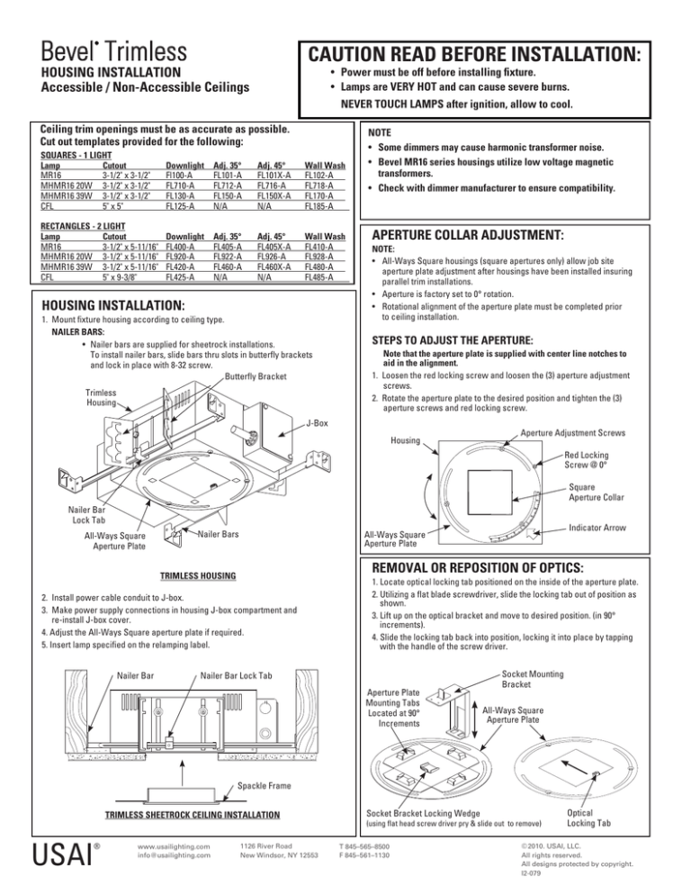
Bevel Trimless ® CAUTION READ BEFORE INSTALLATION: HOUSING INSTALLATION Accessible / Non-Accessible Ceilings • Power must be off before installing fixture. • Lamps are VERY HOT and can cause severe burns. NEVER TOUCH LAMPS after ignition, allow to cool. Ceiling trim openings must be as accurate as possible. Cut out templates provided for the following: SQUARES - 1 LIGHT Lamp Cutout MR16 3-1/2" x 3-1/2" MHMR16 20W 3-1/2" x 3-1/2" MHMR16 39W 3-1/2" x 3-1/2" CFL 5" x 5" Downlight Fl100-A FL710-A FL130-A FL125-A Adj. 35° FL101-A FL712-A FL150-A N/A Adj. 45° FL101X-A FL716-A FL150X-A N/A Wall Wash FL102-A FL718-A FL170-A FL185-A RECTANGLES - 2 LIGHT Lamp Cutout MR16 3-1/2" x 5-11/16" MHMR16 20W 3-1/2" x 5-11/16" MHMR16 39W 3-1/2" x 5-11/16" CFL 5" x 9-3/8" Downlight FL400-A FL920-A FL420-A FL425-A Adj. 35° FL405-A FL922-A FL460-A N/A Adj. 45° FL405X-A FL926-A FL460X-A N/A Wall Wash FL410-A FL928-A FL480-A FL485-A HOUSING INSTALLATION: 1. Mount fixture housing according to ceiling type. NAILER BARS: • Nailer bars are supplied for sheetrock installations. To install nailer bars, slide bars thru slots in butterfly brackets and lock in place with 8-32 screw. Butterfly Bracket Trimless Housing NOTE • Some dimmers may cause harmonic transformer noise. • Bevel MR16 series housings utilize low voltage magnetic transformers. • Check with dimmer manufacturer to ensure compatibility. APERTURE COLLAR ADJUSTMENT: NOTE: • All-Ways Square housings (square apertures only) allow job site aperture plate adjustment after housings have been installed insuring parallel trim installations. • Aperture is factory set to 0° rotation. • Rotational alignment of the aperture plate must be completed prior to ceiling installation. STEPS TO ADJUST THE APERTURE: Note that the aperture plate is supplied with center line notches to aid in the alignment. 1. Loosen the red locking screw and loosen the (3) aperture adjustment screws. 2. Rotate the aperture plate to the desired position and tighten the (3) aperture screws and red locking screw. J-Box Housing Aperture Adjustment Screws Red Locking Screw @ 0° Square Aperture Collar Nailer Bar Lock Tab All-Ways Square Aperture Plate Nailer Bars REMOVAL OR REPOSITION OF OPTICS: TRIMLESS HOUSING 2. Install power cable conduit to J-box. 3. Make power supply connections in housing J-box compartment and re-install J-box cover. 4. Adjust the All-Ways Square aperture plate if required. 5. Insert lamp specified on the relamping label. Nailer Bar Indicator Arrow All-Ways Square Aperture Plate 1. Locate optical locking tab positioned on the inside of the aperture plate. 2. Utilizing a flat blade screwdriver, slide the locking tab out of position as shown. 3. Lift up on the optical bracket and move to desired position. (in 90° increments). 4. Slide the locking tab back into position, locking it into place by tapping with the handle of the screw driver. Socket Mounting Bracket Nailer Bar Lock Tab Aperture Plate Mounting Tabs Located at 90° Increments All-Ways Square Aperture Plate Spackle Frame TRIMLESS SHEETROCK CEILING INSTALLATION Socket Bracket Locking Wedge (using flat head screw driver pry & slide out to remove) ® USAI www.usailighting.com info@usailighting.com 1126 River Road New Windsor, NY 12553 T 845–565–8500 F 845–561–1130 Optical Locking Tab © 2010. USAI, LLC. All rights reserved. All designs protected by copyright. I2-079 Bevel Trimless ® CAUTION READ BEFORE INSTALLATION: INSTALLATION / LAMP ADJUSTMENT Accessible / Non-Accessible Ceilings • Power must be off before installing fixture. • Lamps are VERY HOT and can cause severe burns. NEVER TOUCH LAMPS after ignition, allow to cool. SPACKLE FRAME TRIMLESS INSTALLATION: 1. Using the cut out template supplied, mark the mounting holes on the ceiling. 2. Using a 1/4" diameter bit, carefully drill the mounting holes through the ceiling only. (DO NOT DRILL INTO THE FIXTURE). 3. Position spackle frame into aperture hole and attach utilizing the (4) 8-32 undercut screws. 8-32 x 1-1/4" Undercut Screw Only (4) Places 8-32 Cage Nut PERFORATED SPACKLE FRAME 8-32 x 1-1/4" Undercut Screw 5/8" Min. Ceiling Thickness Joint Compound 4. Ensure the spackle/overspray protector is in place. 5. Apply joint compound over plaster frame and feather out accordingly. 6. Once the ceiling has been sanded and painted, remove the overspray protector, and insert the lamp. NOTE: The spackle frames are directional and must be installed and oriented correctly prior to spackling. ADJUSTABLE FIXTURE: Can be aimed and locked and must be done prior to trim installation. 1. For biased type 45° adjustable and wall wash trims, it may be necessary to orient socket plate and trim at 90° increments. This can be done by re-positioning of the socket/ optics. Please follow instruction REMOVAL OR REPOSITION OF OPTICS (on page 1) to reposition the socket/optics to desired 90° rotational position. 2. Downlight type 35° adjustable trims will rotate 360° within the housing and can be locked horizontally, no indexing required. NOTE: 2 light fixtures may require re-indexing of aperture plate to housing when re-indexing trims - except for 2 light CFL trims which can only be indexed by re-orienting complete housing assembly above ceiling. Housing 45° HOT AIMING/ SELF LOCKING MECHANISM: NOTE: Aiming of lamp is achieved with a #2 Philips head screw driver. 1. Look into the aperture opening and locate the 2 gears. 2. Utilizing a #2 Philips screw driver insert in to desired tilt gear (vertical or horizontal) and turn to desired aiming position. 3. Remove the screwdriver and insert the trim. NOTE: It is important that the glass on the biased trim is facing the lamp. Horizontal Tilt Adjustment Gear 1. Look into the aperture opening and locate the 2 Philips head screws. 2. Loosen the vertical adjustment screw and tilt to desired aiming position and lock with screw driver. 3. Loosen the horizontal rotation locking screw, rotate to desired position and lock with screw driver. Lamp Socket Vertical Tilt Locking Screw Aperture Opening Lamp Shield (35° adj. only) Biased Cut Style Trim 35° LOCKING AIMING ADJUSTMENT MECHANISM: Vertical Tilt Adjustment Gear Lamp Socket Aperture Opening Horizontal Rotation Locking Screw IMPORTANT LAMPING INSTRUCTIONS FOR COMPACT FLUORESCENT BEVELS: Retaining Spring 1 LAMP CFL: • For 1 lamp CFL Bevels, install lamp into socket base 2 LAMP CFL: • For 2 lamp CFL, install lamp into socket base. To re-lamp, hinge lamp downward (as shown) and remove lamp . • To re-install lamp, hinge back up to engage base into retaining spring. ® USAI www.usailighting.com info@usailighting.com 1126 River Road New Windsor, NY 12553 Hinge Down Lamp Base T 845–565–8500 F 845–561–1130 Remove Lamp © 2010. USAI, LLC. All rights reserved. All designs protected by copyright. I2-079


