Compact Fluorescent, Regressed, Flanged, Non-IC
advertisement

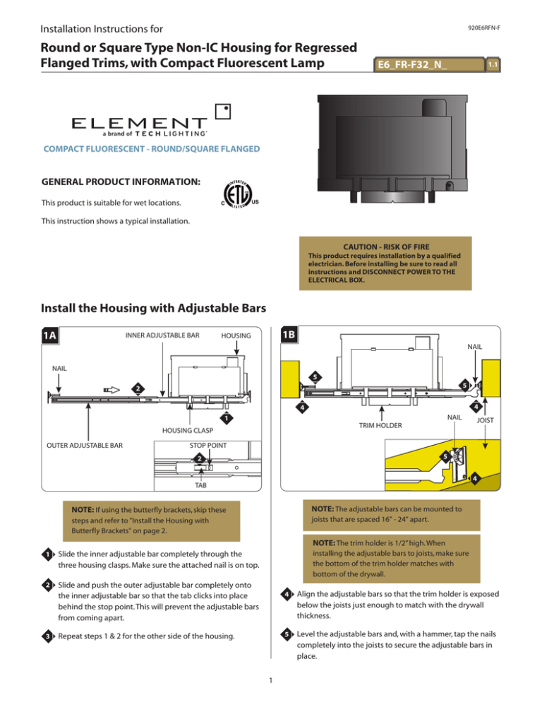
Installation Instructions for 920E6RFN-F Round or Square Type Non-IC Housing for Regressed Flanged Trims, with Compact Fluorescent Lamp E6_FR-F32_N_ 1.1 COMPACT FLUORESCENT - ROUND/SQUARE FLANGED GENERAL PRODUCT INFORMATION: This product is suitable for wet locations. This instruction shows a typical installation. CAUTION - RISK OF FIRE This product requires installation by a qualified electrician. Before installing be sure to read all instructions and DISCONNECT POWER TO THE ELECTRICAL BOX. Install the Housing with Adjustable Bars 1A INNER ADJUSTABLE BAR 1B HOUSING NAIL NAIL 5 5 2 4 4 NAIL 1 OUTER ADJUSTABLE BAR JOIST TRIM HOLDER HOUSING CLASP STOP POINT 5 2 4 TAB NOTE: If using the butterfly brackets, skip these NOTE: The adjustable bars can be mounted to steps and refer to "Install the Housing with Butterfly Brackets" on page 2. joists that are spaced 16" - 24" apart. NOTE: The trim holder is 1/2” high. When 1 Slide the inner adjustable bar completely through the three housing clasps. Make sure the attached nail is on top. 2 Slide and push the outer adjustable bar completely onto the inner adjustable bar so that the tab clicks into place behind the stop point. This will prevent the adjustable bars from coming apart. 3 installing the adjustable bars to joists, make sure the bottom of the trim holder matches with bottom of the drywall. Repeat steps 1 & 2 for the other side of the housing. 1 4 Align the adjustable bars so that the trim holder is exposed below the joists just enough to match with the drywall thickness. 5 Level the adjustable bars and, with a hammer, tap the nails completely into the joists to secure the adjustable bars in place. Install the Housing with Butterfly Brackets 1C 2A 6 HOUSING ADJUSTABLE BAR SLOT 2 WING NUT TRIM HOLDER NOTCH BEVELED CORNER 1 BUTTERFLY BRACKET 7 NOTCH NOTE: Skip to Page 3 if installing the housing with adjustable bars. 1 Loosen (Do not remove) the wing nut. 2 Slip the button head screw through the large opening in the housing slot. Make sure the beveled corners of the butterfly bracket are toward the bottom of the housing. 3 Slide the butterfly bracket within the slot to the desired height, and tighten the wing nut to secure the bracket. 4 Repeat steps 1-3 for the other side. 5 Use the butterfly brackets to mount the housing, according to local building codes and electrical codes. HOUSING TRIM HOLDER SELF TAPPING SCREW 7 6 Adjust the horizontal position of the trim holder by sliding the housing on adjustable bars. 7 When the desired location is achieved, tighten the two selftapping screws to lock the housing onto the adjustable bars. NOTE: Notches in trim holder can be used to align multiple housings using a laser or string. NOTE: Notches in trim holder can be used to align multiple housings using a laser or string. 2 Connect Power to the Housing 3C 3A TABS 4 ELECTRICAL BOX COVER 1 5 Push up the tabs on the electrical box and remove the electrical box cover. 1 6 4 Connect the neutral power line wire to the white ballast wire with the included lever nut. 5 Connect the hot power line wire to the black ballast wire with the included lever nut. 6 Connect the green wire and bare wire to a suitable ground according to local electrical codes. 7 Replace the electrical box cover. Make sure that the top edge of the cover snaps under the tabs. 3B CONDUIT 2 3 NOTE: Before installing drywall or acoustic panel, power up and run the Element fixture(s) for 10 minutes to make sure that all electrical connections are tight and secure. Refer to page 5 to install the lamp for testing. 2 Install the conduit to the housing electrical box. 3 Run the power line wires into the housing electrical box. WARNING: RISK OF FIRE. When using the housing electrical box for power feed through, use MAX 8 - #12 AWG branch circuit wires. 3 Install Drywall or Suspended Ceiling Install the Trim and Lamp 4A 5A 6-3/8" 6-3/8" CLIP 1a 1b REFLECTOR ROUND TRIM HOLDER 1 SQUARE TRIM HOLDER NOTE: This section illustrates a square trim. Round trim pieces install the same way. 1a For housings with round trim holder, mark a 6-3/8" diameter circle on drywall or acoustic panel. Cut out the marked section. 1 1b For housings with square trim holder, mark a 6-3/8" square Turn the reflector clips 90 degrees and lower the reflector from the fixture. Use a flathead screwdriver or pliers to turn the clips if they are too difficult to turn by hand. on drywall or acoustic panel. Cut out the marked section. 5B 4B HOOP (INSIDE) CARABINER SAFETY CABLE DRYWALL 2 Align the cut out section of drywall or acoustic panel with the trim holder and install drywall or acoustic panel. HOOP WARNING: Risk of Fire: The housing is not intended to be in contact with or covered with combustible materials and insulation. Do not install insulation within 3 inches of the housing sides or above in such a manner to entrap heat. CARABINER SAFETY CABLE 2 4 Clip the carabiner onto the hoop inside the housing. Replacing the Lamp 5C 6A CLIP LENS REFLECTOR 3 3 1 Return the reflector to the housing and turn the clips 90 degrees to secure it. 5D LIP 1 Push up slightly on the lens to reveal the inside lip. 2 Grab the trim by the lip and pull the trim out of the trim holder. 3 Unplug the lamp and follow steps 4-5 in section 5 to replace the lamp. LAMP 4 SAFETY CABLE SAVE THESE INSTRUCTIONS! 4 Push the lamp base completely into the socket. Use MAX 32 Watt GX24Q-3 Base Compact Fluorescent Lamp. 5E 5 5 Line up the trim with the trim holder, and push the trim completely into the trim holder. Arrows on the trim and in the trim holder indicate the proper orientation. 5 NOTES 6 7 7400 Linder Ave, Skokie, IL 60077 847.410.4400 www.element-lighting.com © 2008 Tech Lighting, L.L.C. All rights reserved. The "Element" graphic is a registered trademark of Element. Element reserves the right to change specifications for product improvements without notification. A Generation Brands Company 8


