ANZ572 - L-3 Communications
advertisement

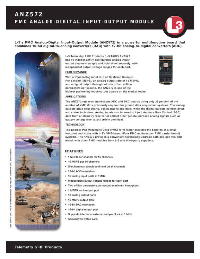
ANZ572 PMC ANALOG-DIGITAL INPUT-OUTPUT MODULE L-3’s PMC Analog-Digital Input-Output Module (ANZ572) is a powerful multifunction board that combines 16-bit digital-to-analog converters (DAC) with 12-bit analog-to-digital converters (ADC). L-3 Telemetry & RF Products (L-3 T&RF) ANZ572 has 16 independently configurable analog input/ output channels sample and hold simultaneously, with independent output voltage ranges for each port. PERFORMANCE With a total analog input rate of 16 Million Samples Per Second (MSPS), an analog output rate of 16 MSPS, and a digital output throughput rate of two million parameters per second, the ANZ572 is one of the highest performing input-output boards on the market today. APPLICATIONS The ANZ572 replaces stand-alone ADC and DAC boards using only 25 percent of the number of VME slots previously required for ground data acquisition systems. The analog outputs drive strip charts, oscillographs and dials, while the digital outputs control lamps and status indicators. Analog inputs can be used to inject Antenna Gain Control (AGC) data from a telemetry receiver or collect other general purpose analog signals such as battery voltage from a test article umbilical. TECHNOLOGY Use of U.S. DoD visual information does not imply or constitute DoD endorsement. The popular PCI Mezzanine Card (PMC) form factor provides the benefits of a small footprint and works with L-3’s VME-based (Four PMC modules per PMC carrier board) systems. The ANZ572 provides a convenient technology upgrade path and can mix-andmatch with other PMC modules from L-3 and third-party suppliers. FEATURES • 1 MSPS per channel for 16 channels • 16 MSPS per 16 channels • Simultaneous sample and hold on all channels • 12-bit ADC resolution • 16 analog input ports at 1MHz • Independent output voltage ranges for each port • Two million parameters per second maximum throughput • 1 MSPS each output port • 16 analog output ports • 16 MSPS output total • 16-bit DAC resolution • 16-bit digital output port • Supports internal or external sample clock at 1 MHz • Accuracy to within 0.2% Telemetry & RF Products ANZ572 PMC ANALOG-DIGITAL INPUT-OUTPUT MODULE SPECIFICATIONS Analog Output Ports Digital Output Ports Ports per module 16 Resolution ~ 0.3 mV Range Each port independent; ±10 V, ±5 V, 0 to 10 V, 0 to 5 V software selectable Output current ±10 mA (typical) continuous,short circuit protected Output impedance 600 Ω Reset to 0V System reset or command Absolute accuracy 0.2% (Hi-Z load > 10 MΩ) External Sample Clock Ports per module 16-bits plus strobe Output strobe 200 nsec, positive polarity Output trigger Presence of tag FormatParallel bits Drivers ±24 mA, LVTTL (3.3 V) Maximum throughput rate 2 M parameters per second General Requirements Input frequency 1 MHz Form factor PMC, IEEE 1386-2001 Signal type Differential, LVDS or RS-422 Operating temperature 0 to 55°C Input impedance 100 Ω Relative humidity Signal characteristics Rising edge tracked (PLL), 50% duty cycle clock synthesized from input Connector type clock Diagnostic display Analog Input Ports <90% (non-condensing) Number of channels 16 Typical power 7.3 W ADC resolution 12-bits Input voltage ranges ±10 V, ±5 V, ±2.5 V, 0 to 10 V Sample and hold Simultaneous all channels Maximum currents +5 V @ 0.135 A +3.3 V @ 1.2 A +12 V @ 0.263 A -12 V @ 0.276 A Sample rate 1 MSPS per channel Maximum total input rate 16 MSPS (4 MSPS when used on a VME Mezzanine Carrier) Common mode rejection 80 dB minimum @ 60 Hz 1 Molex 50-pin, 1 triax NDL-Q 4 status LEDs Internal Sample Clock Maximum rate 1 MSPS per channel Minimum rate .1 SPS per channel sample rate Resolution .20 bit divisor Input type Differential (or signal and ground) Input impedance >100 KΩ Differential; > 50 KWΩ Single Ended Accuracy typical 0.2% Channel control Software selectable on a per channel basis Input coupling DC Compatibility Resolution < 0.025% VME Mezzanine Carrier (ZCM596) VME Mezzanine Carrier with Arbiter (ZCA596) VISTA Software Ordering Information ANZ572 Analog-Digital Input-Output Module, PMC (16 Channels) L- 3 Telemet r y & RF Product s 9020 Balboa Avenue San Diego, CA 92123 Tel: 858.694.7500 800.351.8483 1515 Grundy’s Lane Bristol, PA 19007 Tel: 267.545.7000 Email: Sales.TRF@L-3com.com L-3com.com/ TRF This technical data and software is considered as Technology Software Publicly Available (TSPA) as defined in Export Administration Regulations (EAR) Part 734.7-11. Data, including specifications, contained within this document are summary in nature and subject to change at any time without notice at L-3 Communications’ discretion. Call for latest revision. All brand names and product names referenced are trademarks, registered trademarks, or trade names of their respective holders. ML560 Rev F Telemetry & RF Products


