electronic fluorescent controllable ballasts
advertisement

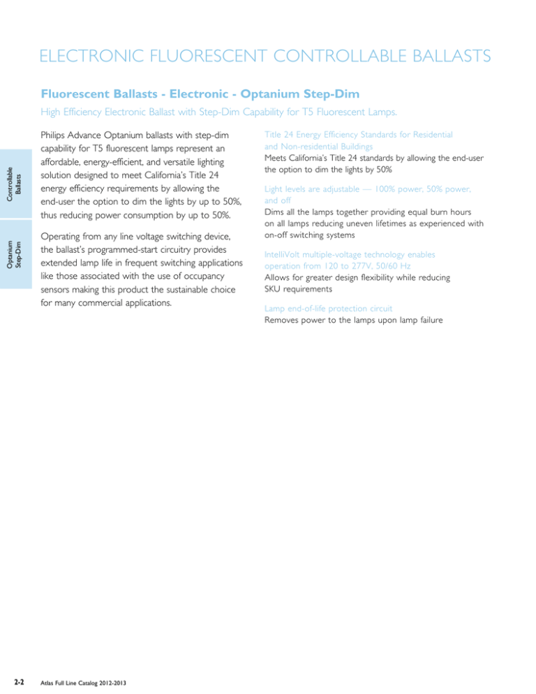
ELECTRONIC FLUORESCENT CONTROLLABLE BALLASTS Fluorescent Ballasts - Electronic - Optanium Step-Dim Optanium Step-Dim Electronic Controllable Fluorescent Controllable BallastsBallasts High Efficiency Electronic Ballast with Step-Dim Capability for T5 Fluorescent Lamps. 2-2 Philips Advance Optanium ballasts with step-dim capability for T5 fluorescent lamps represent an affordable, energy-efficient, and versatile lighting solution designed to meet California’s Title 24 energy efficiency requirements by allowing the end-user the option to dim the lights by up to 50%, thus reducing power consumption by up to 50%. Operating from any line voltage switching device, the ballast’s programmed-start circuitry provides extended lamp life in frequent switching applications like those associated with the use of occupancy sensors making this product the sustainable choice for many commercial applications. Atlas Full Line Catalog 2012-2013 Title 24 Energy Efficiency Standards for Residential and Non-residential Buildings Meets California’s Title 24 standards by allowing the end-user the option to dim the lights by 50% Features Light levels are adjustable — 100% power, 50% power, and off Dims all the lamps together providing equal burn hours on all lamps reducing uneven lifetimes as experienced with on-off switching systems IntelliVolt multiple-voltage technology enables operation from 120 to 277V, 50/60 Hz Allows for greater design flexibility while reducing SKU requirements Lamp end-of-life protection circuit Removes power to the lamps upon lamp failure T5 ELECTRONIC FLUORESCENT CONTROLLABLE BALLASTS For 14 - 35W Lamps HIGH POWER FACTOR SOUND RATED A Optanium Step-Dim Ballast Max/Min No. of Lamps Input Volts Ballast Family Catalog Number Full Light Output Input Power ANSI (Watts) Ballast Factor THD % Line Current (Amps) Min. Starting Temp. (°F/°C) Dim. Wiring Dia. Optanium Electronic Fluorescent Step-Dim Controllable Ballasts Lamp Starting Method F14T5 (14W) 2 120-277 PS Optanium IOP-2S28-115-SC-SD 38/20 1.15/0.48 15 0.32 0/-18 B 173 PS Optanium IOP-2S28-95-SC-SD IOP-2S28-115-SC-SD 45/22 55/27 0.95/0.35 1.15/0.48 10 0.38 0.46 0/-18 B 173 PS IOP-2S28-115-SC-SD Optanium IOP-2S28-95-SC-SD IOP-2S28-115-SC-SD 34/18 57/27 67/33 1.15/0.48 0.95/0.35 1.15/0.48 0.31 0.47 0.55 0/-18 B PS IOP-2S28-115-SC-SD Optanium IOP-2S28-95-SC-SD IOP-2S28-115-SC-SD 37/19 62/30 72/35 1.15/0.48 0.95/0.35 1.15/0.48 0.31 0.52 0.60 0/-18 B PS Optanium IOP-2S28-95-SC-SD IOP-2S28-115-SC-SD 38/19 45/23 0.95/0.35 1.15/0.48 0.32 0.38 0/-18 B F21T5 (21W) 2 120-277 F28T5 (25W) 120-277 2 15 10 Controllable Ballasts 1 170 173 F28T5 (28W) 1 120-277 2 15 10 170 173 F35T5 (35W) 1 120-277 For fixed output version see page 1-31 Power Output Position S1 100% On 50% On 50% Off 0% Off S2 On Power Output 100% 50% 50% 0% LINE B LACK B LACK S1 S2 WHITE YE LLOW Position S1 S2 On On On Off Off On Off Off 15 Line (black ) inputs must be connected to the same phase of the line voltage B LUE B ALLAS T RE D Off BLACK S1 BLACK S2 WHITE BLUE BALLAST RED YELLOW LAMP On LAMP LAMP Off Diag. 170 Line (black) inputs must be connected to Diag . 170 the same phase of the line voltage 1.18" LINE 170 Diag. 173 Line (black) inputs must be connected to the same phase of the line voltage 0" 8.9 " 9.5 1.7 " Fig. B Refer to pages 9-23 to 9-27 for lead lengths and shipping data Atlas Full Line Catalog 2012-2013 2-3 T5/HO ELECTRONIC FLUORESCENT CONTROLLABLE BALLASTS For 24 - 55W Lamps HIGH POWER FACTOR SOUND RATED A Mark 10 Powerline Electronic Dimming Ballast Max/Min Input Volts Ballast Family Catalog Number Input Power ANSI (Watts) Ballast Factor 57/16 1.00/0.05 Full Light Output THD % Line Current (Amps) Min. Starting Temp. (°F/°C) Dim. Wiring Dia. 10 0.48-0.21 50/10 D 153 10 0.49 0.21 0.98 0.42 50/10 D 0.53 0.23 1.05 0.45 50/10 Mark 10Fluorescent Powerline Electronic Controllable Ballasts No. of Lamps Lamp Starting Method F24T5/HO (24W) 120-277 2 PS Mark 10 Powerline IEZ-2S24-D Mark 10 Powerline REZ-154 VEZ-154 REZ-2S54 VEZ-2S54 Mark 10 Powerline REZ-154 VEZ-154 REZ-2S54 VEZ-2S54 Mark 10 Powerline REZ-154 VEZ-154 REZ-2S54 VEZ-2S54 F54T5/HO/ES (49W) 120 1 2 PS 277 59/13 1.00/0.03 117/24 152 Controllable Ballasts 277 120 153 F54T5/HO (54W) 120 1 277 120 2 PS 277 63/13 1.00/0.03 10 125/24 152 D 153 FC12T5/HO (55W) 120 1 277 120 2 PS 277 0.50 0.22 0.96 59/13 0.90/0.03 10 114/24 152 50/10 D 153 0.42 Some lamp manufacturers recommend burning in new lamps 100 hours at full light output before dimming. Consult lamp manufacturer. Ballasts utilizing poke-in connectors can accept wire gauge AWG 16-20. WIRING: (2) QUAD/TRIPLE LAMPS GREEN WHITE LINE BLACK 1.18" DIMMER (1) QUAD/TRIPLE LAMP BLUE BALLAST BLUE YELLOW RED RED GREEN TERMINAL MUST BE GROUNDED 0" 8.9 Diag. 138 " 9.5 1.7 " Diag. 138 DIMMER 1.18" Fig. B 1.00" BLACK/WHITE WHITE BALLAST RED RED BLUE BLUE LAMP 16.70" 16.34" LINE Fig. D Includes connectors with no leads Diag. 152 DIMMER BLACK WHITE RED BALLAST BLUE YELLOW LAMP ONLY USE RAPID-START SOCKETS LAMP Refer to pages 1-15 to 1-19 for information on remote/tandem wiring and lead length extension Refer to pages 2-32 & 2-33 for compatible Mark 10 Powerline controls Refer to pages 9-23 to 9-27 for lead lengths and shipping data LINE Diag. 153 Atlas Full Line Catalog 2012-2013 2-11 ELECTRONIC FLUORESCENT BALLASTS How to Order Philips Lighting Systems and Controls has developed the industry’s broadest distribution system for electronic ballasts. More than 3000 stocking distributors nationwide. For information on the distributor best able to serve your needs, please call 800-372-3331. Electronic Fluorescent Ballasts Ordering Information Electronic Ballast Part Number Breakdown I CF – 2 S 26 – H1 – LD CFL Mounting/Connector Options BL = Bottom leads BLS = Bottom leads with mounting studs BS = Bottom mounting studs with single entry color coded connectors EL = End leads LD = Length mounting feet with SmartMate® dual entry color coded connectors QS = QuikStart Linear Fluorescent Mounting/Connector Options 2LS = 2 Level Switching CFL Can Desription H1 = Hybrid metal / plastic case, size 1 M1 = Metal case, size 1 M2 = Metal case, size 2 M3 = Metal case, size 3 M4 = Metal case, size 4 M5 = Metal case, size 5 M6 = Metal case, size 6 Linear Fluorescent Can Desription 90C = 90°C maximum case temperature rating A = ‘A’ can D = ‘D’ can G = ‘G’ can HL = High light output L = ‘L’ can LW = Low watt MC = Micro can N = ‘N’ can SC = Small can Corporate Offices (800) 322-2086 Customer Support/Technical Service (800) 372-3331 (+) 1 847 390-5000 (International) Visit our web site at www.philips.com/advance Lamp Watts (Primary lamp) Wiring Configuration D = 2D, series M = Modified parallel** P = Parallel PSP = Programmed Start Parallel Q = Quad CFL, series S = Series T = Triple CFL, series TTS = Long twin tube, series TTP = Long twin tube, parallel Maximum Number of Lamps Family Name CF = Compact Fluorescent DA = ROVR EB = AmbiStar EZ = Mark 10® Powerline MB = AmbiStar TR = EssentiaLine Powerline ZT = Mark 7® 0-10V CN = Centium DL = ROVR ELB = AmbiStar LV = EssentiaLine 0-10V OP = Optanium UV = PureVolt • Plan your lighting installation carefully; consider using the services of a qualified lighting designer • Consult your local electric utility regarding demand side management rebate programs. • Select the Philips Advance electronic ballast which best matches the requirements of your application. The technical specifications in this catalog (located on pages 9-6 to 9-13) will be useful in obtaining bids from electrical contractors. • Contact your local Philips Lighting distributor. You will find them to be a helpful supplier of both products and information. Input Voltage G = 347V H = IntelliVolt 347V to 480V 50/60 Hz I = IntelliVolt 120V to 277V 50/60 Hz R = 120V V = 277V * Many current and all future electronic ballast part numbers will not use the “RH-TP” suffixes even though these ballasts will be thermally protected. ** Parallel Wiring Configuration. However, if one lamp fails, all other lamps in the circuit will extinguish. Atlas Full Line Catalog 2012-2013 1-11 Electronic Fluorescent Ballasts ELECTRONIC FLUORESCENT BALLASTS Allowed Wiring Configuration Remote (max length) Tandem Through Blue Red Yellow Blue/White Brown Orange Application Note REB-4P32-SC REB-2S13-M6-EL REB-2S18-M6-EL REB-2S26-M6-EL RELB-1S40-SC RELB-2S40-N REZ-132-SC REZ-154 REZ-1Q18-M2-BS REZ-1Q18-M2-LD REZ-1T42-M2-BS REZ-1T42-M2-LD REZ-1TTS40-SC REZ-2Q18-M2-BS REZ-2Q18-M2-LD REZ-2Q26-M2-BS REZ-2Q26-M2-LD REZ-2S32-SC REZ-2S54 REZ-2T42-M3-BS REZ-2T42-M3-LD REZ-2TTS40-SC REZ-3S32-SC RK-2S32-TP RTR-2S32-SC RZT-154 RZT-2S54 VEZ-132-SC VEZ-154 VEZ-1Q18-M2-BS VEZ-1Q18-M2-LD VEZ-1T42-M2-BS VEZ-1T42-M2-LD VEZ-1TTS40-SC VEZ-2Q18-M2-BS VEZ-2Q18-M2-LD VEZ-2Q26-M2-BS VEZ-2Q26-M2-LD VEZ-2S32-SC VEZ-2S54 VEZ-2T42-M3-BS VEZ-2T42-M3-LD VEZ-2TTS40-SC VEZ-3S32-SC VK-2S32-TP VTR-2S32-SC VZT-154 VZT-2S54 VZT-4S32-HL VZT-4PSP32-G VZT-4S32-G No NA NA5 20” Yes Yes 20’ 20’ 20’ 1 No No No5 No No No5 No No No5 20” NA NA4 20” Yes Yes 4’ 10’ 10’ 2 6’ NA NA4 No NA NA5 No NA NA5 6’ NA NA4 No No No5 No No No5 6’ No Yes No Yes Yes 6’ 5’ 6’ 4’ 6’ 4’ 1 3 No No No5 6’ No No5 No No No5 20’ Yes Yes 4’ 20’ 20’ 2 (a) 6’ Yes Yes 6’ 6’ 6’ 1 No NA NA5 No No Yes 5’ 4’ 4’ 3 6’ NA NA4 No NA NA5 No NA NA5 No NA NA5 6’ NA NA4 No No No5 No No No5 6’ No Yes No Yes Yes 6’ 5’ 6’ 4’ 6’ 4’ 1 5 No No No5 6’ No No4 No No No5 20’ Yes Yes 4’ 20’ 20’ 2 (a) 6’ Yes Yes 6’ 6’ 6’ 1 No NA NA5 No No Yes 5’ 4’ 4’ 3 No No Yes 1’ 1.25’ 5.2’ 1.25’ 4.2’ 3 No No Yes 5’ 5’ 1’ 5’ R/W=5’ 3 No No Yes 1’ 1.25’ 5.2’ 1.25’ 4.2’ 3 For nominal input voltage and 25°C ambient temperature. See all notes on page 1-19. 1-18 Maximum Lead Length (Feet) for Tandem or Through Wiring (Total length of all wires between ballast and lamp sockets) Atlas Full Line Catalog 2012-2013


