Simple CAD Drawing
advertisement

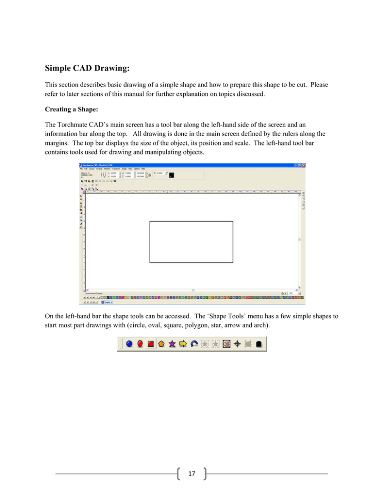
Simple CAD Drawing: This section describes basic drawing of a simple shape and how to prepare this shape to be cut. Please refer to later sections of this manual for further explanation on topics discussed. Creating a Shape: The Torchmate CAD’s main screen has a tool bar along the left-hand side of the screen and an information bar along the top. All drawing is done in the main screen defined by the rulers along the margins. The top bar displays the size of the object, its position and scale. The left-hand tool bar contains tools used for drawing and manipulating objects. On the left-hand bar the shape tools can be accessed. The ‘Shape Tools’ menu has a few simple shapes to start most part drawings with (circle, oval, square, polygon, star, arrow and arch). 17 On the left-hand bar the shape tools can be accessed. The ‘Shape Tools’ menu has a few simple shapes to start most part drawings with (circle, oval, square, polygon, star, arrow and arch). To change the rectangle’s size select it by clicking on the edge of the part, then on the top tool bar type in the ‘X’ and ‘Y’ dimensions that are wanted and press enter. 18 Draw a circle using the same method. Zoom in on the shape by using the ‘Zoom Tools’ pull out along the left-hand tool bar. Next move the circle to position it inside of the rectangle. 19 Once the circle is positioned in the rectangle select both objects, this can be done a few ways. Using the ‘Selection Tools’ from the left-hand toolbar click and drag a blue box around the two objects this will select both of them; another way is to go to ‘Edit’ ‘Select All’. With both objects selected go to ‘Arrange’ ‘Make Path’. This option tells the CAD that all objects selected are one part, allowing the software to determine if something is a hole or cutout. 20 To verify that Torchmate CAD perceives the part as it is intended go to ‘View’ ’Show Fill’ this option displays the part as the computer sees it. With ‘Show Fill’ on the part will fill in what is perceived as the part. Holes should be empty with the metal part filled in. 21 Once the part is finished it can be resized again if necessary, this resizing will adjust the hole’s size along with the part’s size. If the part is the correct size and ‘Show Fill’ appears correct the part is ready to have a tool path created. 22

