Rapid Pressure Rise Relay Datasheet | VIAT Models 950 & 960
advertisement

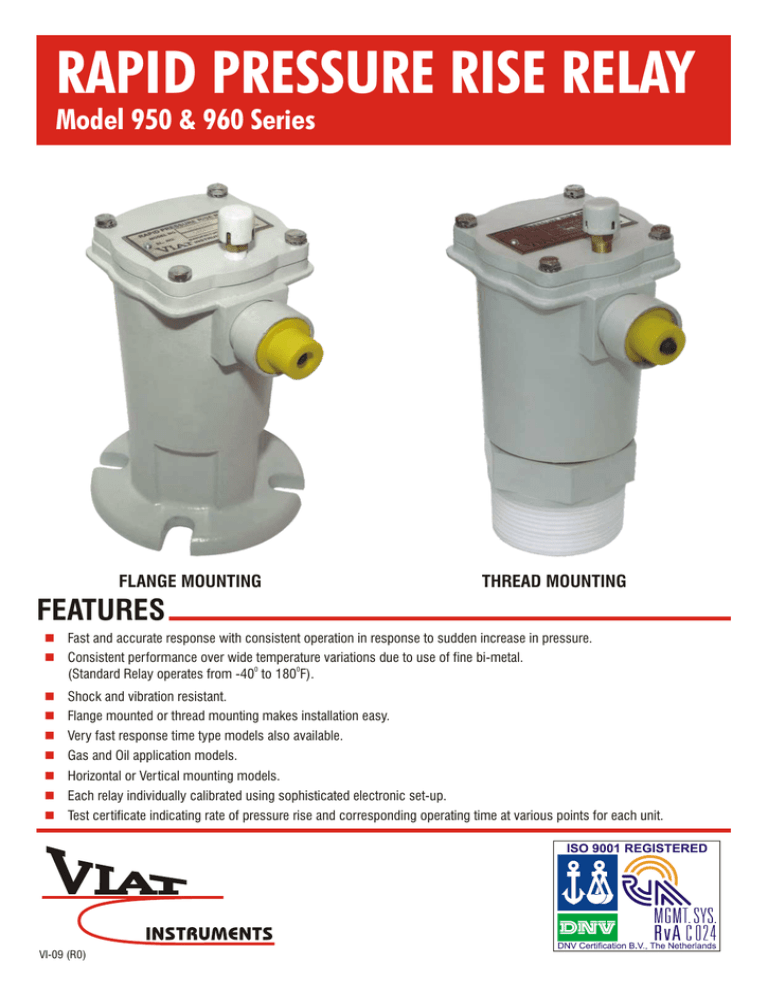
RAPID PRESSURE RISE RELAY Model 950 & 960 Series FLANGE MOUNTING THREAD MOUNTING FEATURES n Fast and accurate response with consistent operation in response to sudden increase in pressure. n Consistent performance over wide temperature variations due to use of fine bi-metal. 0 0 (Standard Relay operates from -40 to 180 F). n Shock and vibration resistant. n Flange mounted or thread mounting makes installation easy. n Very fast response time type models also available. n Gas and Oil application models. n Horizontal or Vertical mounting models. n Each relay individually calibrated using sophisticated electronic set-up. n Test certificate indicating rate of pressure rise and corresponding operating time at various points for each unit. VI-09 (R0) Why RPRR on Transformers? An arcing causes gas to be generated, which in turn starts to build up pressure inside a transformer. Other protection systems like PRD would allow the arcing to increase pressure till the operating pressure of the PRD is reached. This extended period of arcing would have caused some deterioration in the insulation properties of oil and insulation paper. Electrical Switch Connector Actuator Actuator Linkage Control Bellows Control Bellows Housing Control Orifice The VIAT Rapid Pressure Rise Relay (RPRR) gives dynamic protection to oil filled power transformer because it initiates action when the pressure is rising and before it has reached the point where the PRD operates. So the duration of arcing is reducing significantly due to the super fast response of the RPRR. In fact, the RPRR can also be read as Rapid Pressure Response Relay. Sensing Fluid Manifold Bimetal Temperature Compensator Pressure Relief Valve (Optional) Media Sensing Chamber Silicone Fluid Sensing Bellows Protective Shield The VIAT Rapid Pressure Rise Relay, when mounted on the transformer, minimizes the possibility of such occurrences by detecting rates of pressure increase in excess of the safe limits established by the transformer manufacturer. How It Works ? The RPRR operates on the principle of a differential relay, where one bellow responds faster than the other thus causing a differential deflection to the actuator that operates the switch. In a transformer sudden changes in pressure cause the sensing bellow to compress. A little study of adjoining figure would show that the sensing bellow and the control bellows all form a part of a sealed hydraulic system which is filled with silicon oil. One of the control bellows (one on the right of adjoining figure) has unconstrained flow of oil that is rushing from the sensing bellow. In the other bellow the oil has to flow through an orifice and thus the left bellow takes longer time to expand. This causes a disbalance in the actuator and leads to the operation of the switch at unsafe rates of pressure rise. In a few seconds both control bellows will attain equilibrium and the electrical switch inside the relay will automatically reset itself. A fine bimetallic strip with precision screw adjustments is fitted on the orifice. The function of this bimetal is to increase the orifice opening as the temperature drops and reduces the orifice when temperature goes up. This enables the RPRR to function and give consistent results over a wide temperature range. All adjustments are factory set. How to get the best out of RPRR ? A RPRR can be mounted in air (Model 960), under oil (Model 950) and can be mounted both vertically and horizontally. The choice is made by the transformer designer of what to use, how to mount depending on the design, application and availability of space on the transformer. A third type is the screw type which is always mounted vertically. An optional Pressure Relief Valve is supplied with the Type 950 RPRR. This bleed valve allows the air to be released so that the oil reaches the sensing bellows after the RPRR is securely mounted on the transformer. A few teaspoons of oil should be allowed to flow out of the bleed valve before letting the bleed valve to reset. This will ensure that all air is released from around the bellow and the bellow is in contact with only the insulation liquid. For 960 series (mounted on gas space ) this procedure is not necessary. Care has to be taken that the electrical connector always points downwards for all horizontal mounting relays. The vent cap should always point upwards (skywards) irrespective of RPRR being vertical, horizontal or threaded. An Electronic Seal in Relay with reset push button is available separately to latch the signal from the RPRR. 1000 1000 100 100 Rate (psi/sec) Rate (psi/sec) RAPID PRESSURE RISE RELAY RESPONSE CURVES 10 1 1 .1 .1 .01 .1 1 10 .01 950 Series Response Limits 1 Units are calibrated to trip during extreme pressure situation. n Actuation does not occur under normal pressure variations caused by temperature change, vibration, mechanical shock, or pump surges. Materials Can be subjected to full vacuum or 20 psi positive pressure without damage. Bellows Protective Shield Bleed Valve Finish Control Bellows Fluid Manifold Hardware Housing & Cover Hydraulic Fluid O-Ring Seal Sensing Bellows Brass Stainless Steel Grade 304 Polyester Powder Coat Phosphor Bronze Brass Stainless Steel Grade 304 Die-Cast Aluminium Silicone Oil Fluorocarbon Rubber (Viton) Brass Vent Brass & Copper Four one-half inch diameter bolt slots equally spaced on a 4-inch bolt circle 2½ - 8 NPT tapered pipe male thread with 3 inch hex wrench flat Flange Mount Consistency You Can Depend On Mounting 0 Thread Mount Standard operation from -40 to 180 F (-40 to 820C). Standard Operating Temp. -40 to 1800F (-40 to 820C) Switch Ratings 15 Amp @ 125, 250 480 VAC 0.5 Amp @ 125 VDC (Non-inductive) 0.25 Amp @ 250 VDC (Non-inductive) Multiple Mounting Options n n 10 Technical Specifications n n .1 960 Series Response Limits Reliable Performance n 10 The 950/960 can be mounted either horizontally or vertically, as the situation requires. Both flange mount and thread mount options Operational Confidence n Factory test fixtures are calibrated daily. n Units are serialized and calibration records maintained. Connector Options Technical Specifications Housing VIAT Circular 3 pin ANSI VIAT Circular pin STANDARD Flying Leads Terminal Box External chamber is vented to maintain atmospheric pressure Switch operation not affected when subjected to 50/60 Hz, or whole multiples thereof. Resistance to Vibration NOTE : Vibration amplitude of installed relay should be minimized. The natural frequency of the mounted relay must not be 50/60 Hz, or whole multiples thereof. Maximum Rated Pressure (Sensing Bellows) -14.7 to 20 PSIG 3.75" 3.75" 3.75" LOCK WIRE AND SEAL 3.75" LOCK WIRE AND SEAL 5.00" 2.80" 2.80'' 3.75" 3.75" VENT FEMALE CONNECTOR (SHOWN FOR REFERENCE ONLY) AIR VENT 16/3 TYPE "SO" CABLE 393 DIA.(REFERENCE) AIR VENT PROTECTIVE CAP 8.31" 8.31" 1.25" 8.31" 6.00" Pressure Relief Valve (Optional) PROTECTIVE CAP Pressure Relief Valve (Optional) 3.03 HEX 6" AIR VENT 2.5-8 N.P.T. 1.25" 0.50" 0.5" 6.00" VERTICAL FLANGE MOUNTED 3 PIN CONNECTOR PROTECTIVE CAP HORIZONTAL FLANGE MOUNTED Sl. SWITCH CONNECTION TYPES GREEN BLACK STANDARD WHITE BLACK #2 1 RED 2 3 #1 BLUE ANSI VERTICAL THREAD MOUNTED APPLICATION MOUNTING MOUNTING SWITCH POSITION TYPE MODEL NO. 1. Oil Flange Vertical ANSI 950101 2. Oil Flange Vertical Standard 950102 3. Oil Flange Horizontal ANSI 950201 4. Oil Flange Horizontal Standard 5. Oil Threaded Vertical ANSI 950301 6. Oil Threaded Vertical Standard 950302 7. Gas Flange Vertical ANSI 960101 8. Gas Flange Vertical Standard 960102 9. Gas Flange Horizontal ANSI 960201 10. Gas Flange Horizontal Standard 11. Gas Threaded Vertical ANSI 960301 12. Gas Threaded Vertical Standard 960302 950202 960202 Due to our policy of continuous product improvement, dimensions and designs are subject to change. VIAT INSTRUMENTS PVT. LTD. VIAT AMERICA, INC. 2701 to 2704, Shilpangan Phase-II, Block LB-1 Sector-III, Salt Lake, Kolkata - 700 098, INDIA Phones : (91-33) 9903805104, 23352925 l Fax : (91-33) 23352926 E-mail : viatin@viatin.com l Website : www.viatin.com 30 Shepard, Irvine, CA 92620 Tel: 949-679-0950 Fax: 949-417-1358 E-mail : sales@viatamerica.com Website : www.viatamerica.com
