CHAPTER 26 – DC Circuits
advertisement

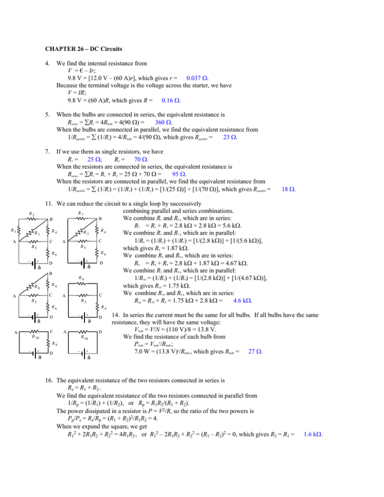
CHAPTER 26 – DC Circuits R1 A A 4. We find the internal resistance from V = € – Ir; 9.8 V = [12.0 V – (60 A)r], which gives r = 0.037 Ω. Because the terminal voltage is the voltage across the starter, we have V = IR; 9.8 V = (60 A)R, which gives R = 0.16 Ω. 5. When the bulbs are connected in series, the equivalent resistance is 360 Ω. Rseries = ∑Ri = 4Rbulb = 4(90 Ω) = When the bulbs are connected in parallel, we find the equivalent resistance from 23 Ω. 1/Rparallel = ∑ (1/Ri) = 4/Rbulb = 4/(90 Ω), which gives Rparallel = 7. If we use them as single resistors, we have R2 = 70 Ω. R1 = 25 Ω; When the resistors are connected in series, the equivalent resistance is Rseries = ∑Ri = R1 + R2 = 25 Ω + 70 Ω = 95 Ω. When the resistors are connected in parallel, we find the equivalent resistance from 1/Rparallel = ∑ (1/Ri) = (1/R1) + (1/R2) = [1/(25 Ω)] + [1/(70 Ω)], which gives Rparallel = 18 Ω. 11. We can reduce the circuit to a single loop by successively combining parallel and series combinations. R7 R2 We combine R1 and R2 , which are in series: B B R7 = R1 + R2 = 2.8 kΩ + 2.8 kΩ = 5.6 kΩ. R4 R4 R3 R3 We combine R3 and R7 , which are in parallel: C 1/R8 = (1/R3) + (1/R7) = [1/(2.8 kΩ)] + [1/(5.6 kΩ)], C A R5 R5 which gives R8 = 1.87 kΩ. R6 R6 We combine R4 and R8 , which are in series: – + – + D D R9 = R4 + R8 = 2.8 kΩ + 1.87 kΩ = 4.67 kΩ. å å We combine R5 and R9 , which are in parallel: B R9 1/R10 = (1/R5) + (1/R9) = [1/(2.8 kΩ)] + [1/(4.67 kΩ)], R4 which gives R10 = 1.75 kΩ. R8 We combine R10 and R6 , which are in series: C C A R5 R5 Req = R10 + R6 = 1.75 kΩ + 2.8 kΩ = 4.6 kΩ. R6 – + å – D C A R6 + å D A R 10 R eq R6 – + å D D – + å 14. In series the current must be the same for all bulbs. If all bulbs have the same resistance, they will have the same voltage: Vbulb = V/N = (110 V)/8 = 13.8 V. We find the resistance of each bulb from Pbulb = Vbulb2/Rbulb ; 7.0 W = (13.8 V)2/Rbulb , which gives Rbulb = 27 Ω. 16. The equivalent resistance of the two resistors connected in series is Rs = R1 + R2 . We find the equivalent resistance of the two resistors connected in parallel from 1/Rp = (1/R1) + (1/R2), or Rp = R1R2/(R1 + R2). The power dissipated in a resistor is P = V2/R, so the ratio of the two powers is Pp/Ps = Rs/Rp = (R1 + R2)2/R1R2 = 4. When we expand the square, we get R12 + 2R1R2 + R22 = 4R1R2 , or R12 – 2R1R2 + R22 = (R1 – R2)2 = 0, which gives R2 = R1 = 1.6 kΩ. I2 R 2 R7 I2 B R1 A I R4 R3 I4 I5 A C R5 R6 I I + – D å R8 I5 C R5 R6 + – D å I4 R9 R4 C R4 R3 B I4 A I5 A R5 R6 I – å A R 10 R6 + D C – å A + – D From above, we have D D R eq R6 I I å C R5 I + B I3 I3 + – å 18. We can reduce the circuit to a single loop by successively combining parallel and series combinations. We combine R1 and R2 , which are in series: R7 = R1 + R2 = 2.20 kΩ + 2.20 kΩ = 4.40 kΩ. We combine R3 and R7 , which are in parallel: 1/R8 = (1/R3) + (1/R7) = [1/(2.20 kΩ)] + [1/(4.40 kΩ)], which gives R8 = 1.47 kΩ. We combine R4 and R8 , which are in series: R9 = R4 + R8 = 2.20 kΩ + 1.47 kΩ = 3.67 kΩ. We combine R5 and R9 , which are in parallel: 1/R10 = (1/R5) + (1/R9) = [1/(2.20 kΩ)] + [1/(3.67 kΩ)], which gives R10 = 1.38 kΩ. We combine R10 and R6 , which are in series: Req = R10 + R6 = 1.38 kΩ + 2.20 kΩ = 3.58 kΩ. The current in the single loop is the current through R6 : I6 = I = V/Req = (12 V)/(3.58 kΩ) = 3.36 mA. For VAC we have VAC = IR10 = (3.36 mA)(1.38 kΩ) = 4.63 V. This allows us to find I5 and I4 ; I5 = VAC/R5 = (4.63 V)/(2.20 kΩ) = 2.11 mA; 1.26 mA. I4 = VAC/R9 = (4.63 V)/(3.67 kΩ) = For VAB we have VAB = I4R8 = (1.26 mA)(1.47 kΩ) = 1.85 V. This allows us to find I3 , I2 , and I1 ; I3 = VAB/R3 = (1.85 V)/(2.20 kΩ) = 0.84 mA; 0.42 mA. I1 = I2 = VAB/R7 = (1.85 V)/(4.40 kΩ) = VAB = 1.85 V. 19. (a) When the switch is closed the addition of R2 to the parallel set will decrease the equivalent resistance, so the current from the battery will increase. This causes an increase in the voltage across R1 , and a corresponding decrease across R3 and R4. The voltage across R2 increases from zero. Thus we have V1 and V2 increase; V3 and V4 decrease. (b) The current through R1 has increased. This current is now split into three, so currents through R3 and R4 decrease. Thus we have I1 (= I) and I2 increase; I3 and I4 decrease. (c) The current through the battery has increased, so the power output of the battery increases. (d) Before the switch is closed, I2 = 0. We find the resistance for R3 and R4 in parallel from 1/RA = ∑ (1/Ri) = 2/R3 = 2/(100 Ω), which gives RA = 50 Ω. For the single loop, we have I = I1 = V/(R1 + RA) = (45.0 V)/(100 Ω + 50 Ω) = 0.300 A. This current will split evenly through R3 and R4 : I3 = I4 = !I = !(0.300 A) = 0.150 A. After the switch is closed, we find the resistance for R2 , R3 , and R4 in parallel from 1/RB = ∑ (1/Ri) = 3/R3 = 3/(100 Ω), which gives RB = 33.3 Ω. For the single loop, we have I = I1 = V/(R1 + RB) = (45.0 V)/(100 Ω + 33.3 Ω) = 0.338 A. This current will split evenly through R2 , R3 , and R4 : I2 = I3 = I4 = ⅓I = ⅓(0.338 A) = 0.113 A. R1 I a I S + V – R2 I3 R3 I4 R4 R2 I3′ R3 I4′ R4 b R1 a I′ V + – I2′ b 20. (a) When the switch is opened, the removal of a resistor from the parallel set will increase the equivalent resistance, so the current from the battery will decrease. This causes a decrease in the voltage across R1 , and a corresponding increase across R2 . The voltage across R3 decreases to zero. R1 a å + – r I I2 R2 I3 R3 b a R1 S + å – r I′ I′ R2 R3 b Thus we have V1 and V3 decrease; V2 increases. (b) The current through R1 has decreased. The current through R2 has increased. The current through R3 has decreased to zero. Thus we have I1 (= I) and I3 decrease; I2 increases. (c) Because the current through the battery decreases, the Ir term decreases, so the terminal voltage of the battery will increase. (d) When the switch is closed, we find the resistance for R2 and R3 in parallel from 1/RA = ∑ (1/Ri) = 2/R = 2/(5.50 Ω), which gives RA = 2.75 Ω. For the single loop, we have I = V/(R1 + RA + r) = (12.0 V)/(5.50 Ω + 2.75 Ω + 0.50 Ω) = 1.37 A. For the terminal voltage of the battery, we have Vab = € – Ir = 12.0 V – (1.37 A)(0.50 Ω) = 11.3 V. (e) When the switch is open, for the single loop, we have I′ = V/(R1 + R2 + r) = (12.0 V)/(5.50 Ω + 5.50 Ω + 0.50 Ω) = 1.04 A. b 29. When we include the current through the battery, we have six unknowns. For the conservation of current, we have junction a: I = I1 + I2 ; junction b: I1 = I3 + I5 ; junction d: I2 + I5 = I4 . For the three loops indicated on the diagram, we have loop 1: – I1R1 – I5R5 + I2R2 = 0; – I1(20 Ω) – I5(10 Ω) + I2(25 Ω) = 0; loop 2: – I3R3 + I4R4 + I5R5 = 0; – I3(2 Ω) + I4(2 Ω) + I5(10 Ω) = 0; loop 3: + € – I2R2 – I4R4 = 0. + 6.0 V – I2(25 Ω) – I4(2 Ω) = 0. R3 R1 I1 a I5 1 R4 d å I When we solve these six equations, we get I1 = 0.274 A, I2 = 0.222 A, I3 = 0.266 A, I4 = 0.229 A, I5 = 0.007 A, I = 0.496 A. We have carried an extra decimal place to show the agreement with the junction equations. + I1 – å1 r1 b 1 R3 I2 + I3 = I1 , or – 0.30 A + I3 = I1 . For the top loop indicated on the diagram, we have loop 1: €1 – I1r1 – I1R3 + €2 – I2r2 – I2R2 – I1R1 = 0; + 12.0 V – I1(1.0 Ω) – I1(8.0 Ω) + 12.0 V – (– 0.30 A)(1.0 Ω) – (– 0.30 A)(10 Ω) – I1(12 Ω) = 0, which gives I1 = 1.30 A. Thus we have I3 = I1 – I2 = 1.30 A – (– 0.30 A) = 1.60 A. For the bottom loop indicated on the diagram, we have loop 2: € – I3r – I3R5 + I2R2 – €2 + I2r2 – I3R4 = 0; €– (1.60 A)(1.0 Ω) – (1.60 A)(18 Ω) + (– 0.30 A)(10 Ω) – 12.0 V + (– 0.30 A)(1.0 Ω) – (1.60 A)(15 Ω) = 0, which gives €= 70 V. 34. For the conservation of current at point a, we have I2 + I3 = I1 . For the two loops indicated on the diagram, we have loop 1: €1 – I1r1 – I1R3 + €2 – I2r2 – I2R2 – I1R1 = 0; + 12.0 V – I1(1.0 Ω) – I1(8.0 Ω) + 12.0 V – I2(1.0 Ω) – I2(10 Ω) – I1(12 Ω) = 0; loop 2: €3 – I3r3 – I3R5 + I2R2 – €2 + I2r2 – I3R4 = 0; + 6.0 V – I3(1.0 Ω) – I3(18 Ω) + I2(10 Ω) – 12.0 V + I2(1.0 Ω) – I3(15 Ω) = 0. When we solve these equations, we get I1 = 0.77 A, I2 = 0.71 A, I3 = 0.055 A. For the terminal voltage of the 6.0-V battery, we have 5.95 V. Vfe = €3 – I3r3 = 6.0 V – (0.055 A)(1.0 Ω) = I4 I2 3 c å 2 r2 R4 R1 R2 g d a 2 I2 å R5 r e f I3 c I1 å1 r1 b 1 R3 d R4 å2 r2 I2 e R1 R2 g a 2 å3 R5 r3 f I3 c 2 R5 R2 33. The given current is I2 = – 0.30 A. For the conservation of current at point a, we have I3 41. (a) We find the capacitance from τ = RC; 55 × 10–6 s = (15 × 103 Ω)C, 3.7 nF. which gives C = 3.7 × 10⁻⁹ F = (b) The voltage across the capacitance will increase to the final steady state value. The voltage across the resistor will start at the battery voltage and decrease exponentially: VR = € e – t/τ ; 16.0 V = (24.0 V)e – t/(55 μs), or t/(55 μs) = ln(24.0 V/16.0 V) = 0.405, which gives t = 22 μs. R – 43. The charge on the capacitor increases with time to a final charge Q0 : Q = Q0 (1 – e – t/τ ). When we express the stored energy in terms of charge we have U = ½CV2 = ½Q2/C = ½(Q02/C)(1 – e – t/τ )2 = Umax(1 – e – t/τ )2. We find the time to reach half the maximum from ½ = (1 – e – t/τ )2, or e – t/τ = 1 – 1/v2, which gives t = 1.23τ. å C S I1 45. (a) For the conservation of current at point a, we have I1 = I2 + I3 . For the loop on the right, we have + I2R2 – Q/C = 0, or I2R2 = Q/C. For the outside loop, we have €– I1R1 – Q/C = 0, or I1R1 = €– Q/C. The current I3 is charging the capacitor: I3 = dQ/dt. When we use these results in the junction equation, we get (€ – Q/C)/R1 = (Q/R2C) + dQ/dt, which becomes € = R1 dQ/dt + (R1 + R2)Q/R2C. This has the same form as the simple RC circuit R1 a å R2 1 C b Vc c I I1 C 1 R1 I2 C 2 R2 Vd (3) (5) (6) I3 b a (1) (2) I3 I2 47. Because we have no simple series or parallel connections, we analyze the circuit. On the diagram, we show the potential difference applied between points c and d, and the four currents. For the conservation of current at points c and d, we have I = I1 + I3 = I2 + I4 . The current I3 is charging the capacitor C1 : I3 = dQ3/dt. The current I4 is charging the capacitor C2 : I4 = dQ4/dt. For a CW loop acba, we have I1R1 – Q3/C1 = 0, or Q3/C1 = (I – I3)R1 = (I – dQ3/dt)R1 . For a CW loop dabd, we have I2R2 – Q4/C2 = 0, or Q4/C2 = (I – I4)R2 = (I – dQ4/dt)R2 . For the path cbd, we have (4) Vcd = (Q3/C1) + (Q4/C2). If we differentiate this, we get dVcd/dt = 0 = (1/C1)(dQ3/dt) + (1/C2)(dQ4/dt), or dQ4/dt = – (C2/C1) dQ3/dt. When we combine (3) and (5), we get Q4/C2 = R2[I + (C2/C1) dQ3/dt]. When we combine (2) and (6), we get Q4/C2 = (R2/R1C1)Q3 + [R2(C1 + C2)/C1] dQ3/dt. (7) When we combine (4) and (7), we get Vcd = [(R1 + R2)/R1C1]Q3 + [R2(C1 + C2)/C1] dQ3/dt. + d I4 This has the same form as the simple RC circuit: € = R dQ/dt + Q/C, with R = R2(C1 + C2)/C1 , and C = R1C1/(R1 + R2). Thus the time constant is τ = R1R2(C1 + C2)/(R1 + R2) = (8.8 Ω)(4.4 Ω)(0.48 μF + 0.24 μF)/(8.8 Ω + 4.4 Ω) = 2.1 μs.


