MICROFLUIDIC SOLUTION ISOLATED PUMPING (µSIP)
advertisement
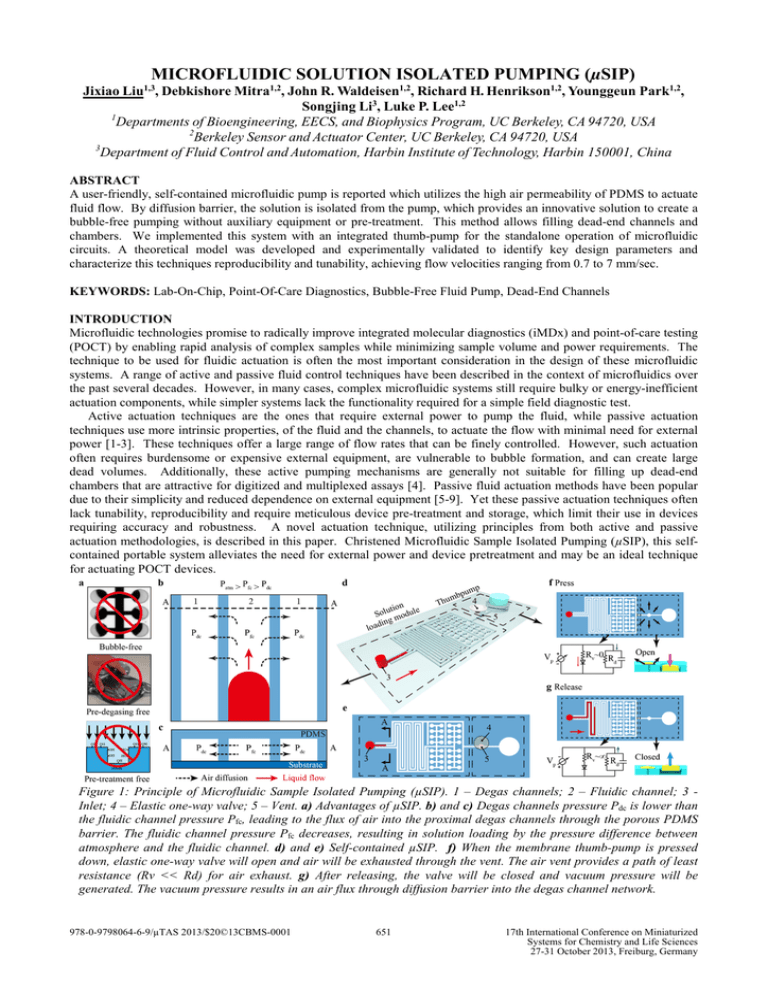
MICROFLUIDIC SOLUTION ISOLATED PUMPING (µSIP) Jixiao Liu , Debkishore Mitra1,2, John R. Waldeisen1,2, Richard H. Henrikson1,2, Younggeun Park1,2, Songjing Li3, Luke P. Lee1,2 1 Departments of Bioengineering, EECS, and Biophysics Program, UC Berkeley, CA 94720, USA 2 Berkeley Sensor and Actuator Center, UC Berkeley, CA 94720, USA 3 Department of Fluid Control and Automation, Harbin Institute of Technology, Harbin 150001, China 1,3 ABSTRACT A user-friendly, self-contained microfluidic pump is reported which utilizes the high air permeability of PDMS to actuate fluid flow. By diffusion barrier, the solution is isolated from the pump, which provides an innovative solution to create a bubble-free pumping without auxiliary equipment or pre-treatment. This method allows filling dead-end channels and chambers. We implemented this system with an integrated thumb-pump for the standalone operation of microfluidic circuits. A theoretical model was developed and experimentally validated to identify key design parameters and characterize this techniques reproducibility and tunability, achieving flow velocities ranging from 0.7 to 7 mm/sec. KEYWORDS: Lab-On-Chip, Point-Of-Care Diagnostics, Bubble-Free Fluid Pump, Dead-End Channels INTRODUCTION Microfluidic technologies promise to radically improve integrated molecular diagnostics (iMDx) and point-of-care testing (POCT) by enabling rapid analysis of complex samples while minimizing sample volume and power requirements. The technique to be used for fluidic actuation is often the most important consideration in the design of these microfluidic systems. A range of active and passive fluid control techniques have been described in the context of microfluidics over the past several decades. However, in many cases, complex microfluidic systems still require bulky or energy-inefficient actuation components, while simpler systems lack the functionality required for a simple field diagnostic test. Active actuation techniques are the ones that require external power to pump the fluid, while passive actuation techniques use more intrinsic properties, of the fluid and the channels, to actuate the flow with minimal need for external power [1-3]. These techniques offer a large range of flow rates that can be finely controlled. However, such actuation often requires burdensome or expensive external equipment, are vulnerable to bubble formation, and can create large dead volumes. Additionally, these active pumping mechanisms are generally not suitable for filling up dead-end chambers that are attractive for digitized and multiplexed assays [4]. Passive fluid actuation methods have been popular due to their simplicity and reduced dependence on external equipment [5-9]. Yet these passive actuation techniques often lack tunability, reproducibility and require meticulous device pre-treatment and storage, which limit their use in devices requiring accuracy and robustness. A novel actuation technique, utilizing principles from both active and passive actuation methodologies, is described in this paper. Christened Microfluidic Sample Isolated Pumping (µSIP), this selfcontained portable system alleviates the need for external power and device pretreatment and may be an ideal technique for actuating POCT devices. Figure 1: Principle of Microfluidic Sample Isolated Pumping (µSIP). 1 – Degas channels; 2 – Fluidic channel; 3 Inlet; 4 – Elastic one-way valve; 5 – Vent. a) Advantages of µSIP. b) and c) Degas channels pressure Pdc is lower than the fluidic channel pressure Pfc, leading to the flux of air into the proximal degas channels through the porous PDMS barrier. The fluidic channel pressure Pfc decreases, resulting in solution loading by the pressure difference between atmosphere and the fluidic channel. d) and e) Self-contained µSIP. f) When the membrane thumb-pump is pressed down, elastic one-way valve will open and air will be exhausted through the vent. The air vent provides a path of least resistance (Rv << Rd) for air exhaust. g) After releasing, the valve will be closed and vacuum pressure will be generated. The vacuum pressure results in an air flux through diffusion barrier into the degas channel network. 978-0-9798064-6-9/µTAS 2013/$20©13CBMS-0001 651 17th International Conference on Miniaturized Systems for Chemistry and Life Sciences 27-31 October 2013, Freiburg, Germany THEORY The principle behind µSIP and representative device design used for the characterization reported in this paper is shown in Figure 1. The basic design of devices employing μSIP consists of two channel networks, the fluidic channel and the degas channel, which are located in close proximity to each other. The fluidic channel, to be loaded with the liquid solution, is surrounded by proximal degas channels that are connected to a vacuum source. Air within the fluidic channel diffuses through the high-permeability PDMS barrier and into the proximal degas channel under the negative pressure gradient when vacuum pressure exerted into degas lines. This consistent outward air transport leads to a reduction in the fluidic channel pressure and the liquid solution is loaded into the device, under the pressure difference between the inlet (which is at atmospheric pressure) and the fluidic channel. The driving force behind flow actuation in μSIP is the reduction in fluidic channel pressure brought about by the diffusion of air into the vacuum/degas channel. And to use Fick’s 1st and 2nd law of diffusion and the ideal gas law, the fluidic channel pressure Pfc can be expressed as a function of design parameters, which include the fluidic channel width w, the thickness of the PDMS barrier (or proximity) d , the diffusion coefficient of air in PDMS D and the air pressure in the degas channel Pdc [10, 11]. Based on it, the NavierStokes equation then could be written as [12]: dL (t ) (1) A( h, w) = µ L (t ) − Pfc ( w, d , D, Pdc , L (t ), t ) + Patm + Pcapillary (σ , θ , w, h ) dt where A(h,w) is a function of h and w and works as a correction coefficient in the equation; Patm is the atmospheric pressure; σ is the surface tension of the fluid; µ is the fluid viscosity; and θ is the contact angle. From equation (1), it could be suggested that the μSIP performance could be effected and also tuned by changing either the design parameters or the sample properties, which is also the theoretical basis of the developed simulation and experiment in this paper. EXPERIMENTAL A multiphysics simulation model for µSIP was implemented in combined COMSOL - MATLAB mode to characterize the effects that different device design parameters have on fluid flow. For the experimental characterization, firstly a tunable vacuum source was connected with the degas channels on the devices, and then an membrane thumb-pump was integrated as an on-chip vacuum source to achieve standalone operation. Based on the previous theoretical model, the main design parameters varied for the both simulation and experimental characterization study were the proximity between the two channel networks d, fluidic channel width w, and applied vacuum pressure in the degas channel network Pdc. And to demonstrate the bubble-free loading, self-contained device with integrated thumb-pump was tested. Figure 2: Simulation and experimental results of µSIP. a) Cross-section of the channel networks, which indicates the parameters varied in the characterizations. b) to d) Simulation and experimental data of different parameters: Proximity d, degas channel vacuum pressure Pdc and channel width w. Those parameters effect the liquid flow in different levels. Dotted lines represent simulation results and solid lines experiment data. Properties of water was employed during simulation while food color solution was used during experiments for ease of visualization. Figure 3: Self-contained µSIP liquid loading. a) Image of the tested device. The thumb-pump was assisted with an elastic one-way valve to work as an on-chip vacuum source. b) Microscopic image of self-contained µSIP chip. Demonstrated chip consists of 170 mm long channels and 880 dead-end chambers, which could be fully loaded within 2 minutes by finger press-release operation. c) Fluidic channels were loaded with red food dye. Arrows indicate the degas channels which surround the fluidic channels. d) Fully loaded dead-end chambers and surrounding degas channels. 652 RESULTS AND DISCUSSION The results of the simulation and experimental characterization of µSIP is shown in Figure 2. The experimental data validated the simulation model developed, with deviation between the two arising due to the slight differences in fluid properties, such as viscosity, density, contact angle, and surface tension between water (used in the simulation model) and the food dye solution (used in the experimental characterization). The observed effects of the various design parameters (Figure 2 b - d), on fluid flow behavior, corroborated the theoretical predictions. The simulation and experimental result suggested that the fluid loading performance could be tuned by varying these parameters, thus achieving a wide range of degas pressures and flow velocities (a range of 0.7 – 7 mm/sec observed), still, larger performance range would be feasible by combining different parameter variations. The main advantages of the μSIP technique, when compared to other active flow actuation methods, are the capabilities for bubble-free solution loading and the filling of dead-end channels/chambers without air voids or cavitation. These competences were demonstrated in Figure 3 by using self-contained µSIP that integrated with thumb-pump. There are 170 mm long channel and 880 dead-end chambers on-chip and the whole chip could be loaded within 2 minutes without leaving any air bubbles, as shown in Figure 3 c and d. It is also possible to tune the performance by changing the thumb-pump parameters, such as chamber and membrane dimensions. The variation of thumb-pump diameters could vary the vacuum pressure generated by finger press-release. Dead-end structures can be filled completely using μSIP, which is of great significance for performing digitized microfluidic molecular biology assays. And the competence of selfcontained flow actuation will be greatly beneficial to those technologies requiring on-site applications. CONCLUSION In conclusion, we report here the development of a power-free, portable, and tunable µSIP method for microfluidic actuation. It does not require auxiliary power source, or device pre-treatment for energy deposit and surface treatment. Our characterization studies demonstrate the capacity of this method for rapid, tunable, bubble-free actuation, making this system ideal for a variety of applications. One such application is in the field of POCT, where a portable, robust and tunable fluidic actuation technique requiring almost no power will be crucial for the development of high-density microfluidic testing chips which can be deployed to the field. We also anticipate the future use of µSIP devices for digital bioassays and integrated molecular diagnostic devices. ACKNOWLEDGEMENTS The authors would like to thank the BioPOETS group at U.C. Berkeley for the help and support. The authors acknowledge the Bill & Melinda Gates Foundation (Global Health Grant: OPP1028785) for funding this work. Jixiao Liu would like to thank China Scholarship Council for the support. REFERENCES [1] Weng, C.H., et al., A suction-type, pneumatic microfluidic device for liquid transport and mixing. Microfluidics and Nanofluidics, 2011. 10(2): p. 301-310. [2] Persat, A., R.D. Chambers, and J.G. Santiago, Basic principles of electrolyte chemistry for microfluidic electrokinetics. Part I: Acid-base equilibria and pH buffers. Lab on a Chip, 2009. 9(17): p. 2437-2453. [3] Gorkin, R., et al., Centrifugal microfluidics for biomedical applications. Lab on a Chip, 2010. 10(14): p. 1758-1773. [4] Ottesen, E.A., et al., Microfluidic digital PCR enables multigene analysis of individual environmental bacteria. Science, 2006. 314(5804): p. 1464-1467. [5] Juncker, D., et al., Autonomous Microfluidic Capillary System. Analytical Chemistry, 2002. 74(24): p. 6139-6144. [6] Hosokawa, K., et al., Power-free poly(dimethylsiloxane) microfluidic devices for gold nanoparticle-based DNA analysis. Lab on a Chip, 2004. 4(3): p. 181-185. [7] Dimov, I.K., et al., Stand-alone self-powered integrated microfluidic blood analysis system (SIMBAS). Lab on a Chip, 2011. 11(5): p. 845-850. [8] Yao, B., et al., A microfluidic device based on gravity and electric force driving for flow cytometry and fluorescence activated cell sorting. Lab on a Chip, 2004. 4(6): p. 603-607. [9] Walker, G.M. and D.J. Beebe, An evaporation-based microfluidic sample concentration method. Lab on a Chip, 2002. 2(2): p. 57-61. [10] Carslaw, H. and J. Jaeger, Conduction of Heat in Solids (paperback). 1959. [11] Crank, J., The mathematics of diffusion. 1979: Oxford university press. [12] Bruus, H., Theoretical microfluidics. Vol. 18. 2007: OUP Oxford. CONTACT * L.P. Lee, tel: +1-510-642-5855; lplee@berkeley.edu 653
