10.4: Wide Viewing Angle Photoaligned Plastic Films for TN
advertisement

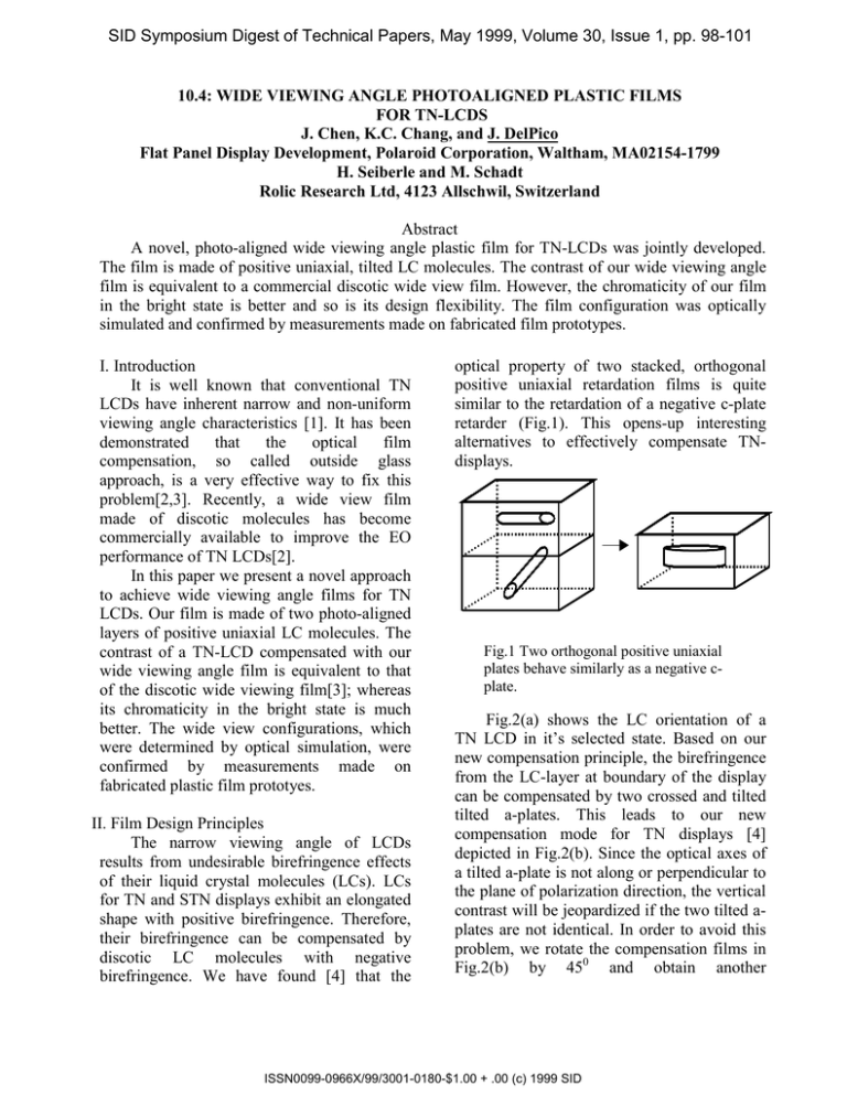
SID Symposium Digest of Technical Papers, May 1999, Volume 30, Issue 1, pp. 98-101 10.4: WIDE VIEWING ANGLE PHOTOALIGNED PLASTIC FILMS FOR TN-LCDS J. Chen, K.C. Chang, and J. DelPico Flat Panel Display Development, Polaroid Corporation, Waltham, MA02154-1799 H. Seiberle and M. Schadt Rolic Research Ltd, 4123 Allschwil, Switzerland Abstract A novel, photo-aligned wide viewing angle plastic film for TN-LCDs was jointly developed. The film is made of positive uniaxial, tilted LC molecules. The contrast of our wide viewing angle film is equivalent to a commercial discotic wide view film. However, the chromaticity of our film in the bright state is better and so is its design flexibility. The film configuration was optically simulated and confirmed by measurements made on fabricated film prototypes. I. Introduction It is well known that conventional TN LCDs have inherent narrow and non-uniform viewing angle characteristics [1]. It has been demonstrated that the optical film compensation, so called outside glass approach, is a very effective way to fix this problem[2,3]. Recently, a wide view film made of discotic molecules has become commercially available to improve the EO performance of TN LCDs[2]. In this paper we present a novel approach to achieve wide viewing angle films for TN LCDs. Our film is made of two photo-aligned layers of positive uniaxial LC molecules. The contrast of a TN-LCD compensated with our wide viewing angle film is equivalent to that of the discotic wide viewing film[3]; whereas its chromaticity in the bright state is much better. The wide view configurations, which were determined by optical simulation, were confirmed by measurements made on fabricated plastic film prototyes. II. Film Design Principles The narrow viewing angle of LCDs results from undesirable birefringence effects of their liquid crystal molecules (LCs). LCs for TN and STN displays exhibit an elongated shape with positive birefringence. Therefore, their birefringence can be compensated by discotic LC molecules with negative birefringence. We have found [4] that the optical property of two stacked, orthogonal positive uniaxial retardation films is quite similar to the retardation of a negative c-plate retarder (Fig.1). This opens-up interesting alternatives to effectively compensate TNdisplays. Fig.1 Two orthogonal positive uniaxial plates behave similarly as a negative cplate. Fig.2(a) shows the LC orientation of a TN LCD in it’s selected state. Based on our new compensation principle, the birefringence from the LC-layer at boundary of the display can be compensated by two crossed and tilted tilted a-plates. This leads to our new compensation mode for TN displays [4] depicted in Fig.2(b). Since the optical axes of a tilted a-plate is not along or perpendicular to the plane of polarization direction, the vertical contrast will be jeopardized if the two tilted aplates are not identical. In order to avoid this problem, we rotate the compensation films in Fig.2(b) by 450 and obtain another ISSN0099-0966X/99/3001-0180-$1.00 + .00 (c) 1999 SID compensation mode shown in Fig.2(c). As long as the average tilt angle equals that of a uniformly tilted a-plate, the uniformly tilted a- plates in Fig.2b can also be replaced by aplates with splayed configurations. 0 0 0 0 0 (20 ,45 ) (20 ,0 ) 0 0 0 (20 ,90 ) (20 ,135 ) z z y y x x 0 0 0 0 (b) 0 (20 ,135 ) 0 (20 ,180 ) (a) 0 (20 ,45 ) 0 (20 ,90 ) (c) Fig.2(a) LC-Orientation in a TN-LCD in the selected state. (b) New compensation mode for TNLCDs. θ, φ are the tilt- and the azimuthal angle orientation of the optical axis of the tilted a-plate. (c) Modified compensation mode following from configuration (b). Table I. Parameters Used in Wide View Film Simulations for TN-LCD. Front Polarizer Rear Polarizer Nitto Denko’s 1220DU, Transmission axis 45deg Nitto Denko’s 1220DU, Transmission axis 135deg TAC film attached to Polarizer nx=ny and (nx-nz)d=60nm Liquid Crystal parameters Tilted a-plate Buffing direction:45deg(front) and 315deg(rear) εp=10.5, εs=4.8, no=1.478, ne=1.568, d=4.5um, pretilt=5deg, K1=10.2, K2=5.6, K3=15.6 and d/p=-0.03 Pretilt angle=20deg, (ne-no)d=60nm ISSN0099-0966X/99/3001-0180-$1.00 + .00 (c) 1999 SID compensated by a discotic film, was calculated for various applied voltages (Fig.4). From the comparison follows, that the color shift of our novel compensation films is much smaller than that of discotic films. Color Coordinate III. Results and Discussions The following optical simulations refer to the compensated TN modes shown in Figs.2(b)(c). The LC-material parameters used are listed in Table I. Our simulations show that good viewing angle characteristics can be accomplished if tilt angle θ and optical retardation (ne-no)d of the tilted a-plate are chosen 200 and 60nm respectively. The calculated results under these compensation conditions are shown in Fig.3. For comparison, the color coordinates of a TN-LCD in the horizontal viewing plane at 600, which was 0.43 0.42 0.41 0.4 0.39 0.38 0.37 0.36 x y 1 1.25 1.5 1.75 2 Color Coordinate Voltage(v) (a) 0.43 0.42 0.41 0.4 0.39 0.38 0.37 0.36 x y 1 1.25 1.5 1.75 2 Voltage(v) Fig.4 Color coordinates at 600 view in the horizontal plane versus applied voltage. Top: Novel Polaroid film, Bottom: Discotic film. (b) Fig.3 (a) and (b): Calculated viewing angle characteristic of a TN-LCD based on our compensation configurations Fig.2(b) and Fig.2(c) respectively. The maximum of polar angle is 600. The TN wide viewing angle films on plastic substrates are based on Rolic’s linearly photopolymerizable (LPP) photo-aligning technology [5,6]. Due to the contact free alignment, the LPP-technology is ideally suited for roll to roll processes. In a first step, the LPP-photo-polymer was coated on an optically isotropic plastic film and subsequently exposed to obliquely incident linearly polarized UV-light. This generates a 50nm thin, uniaxial LPP-alignment layer which induces a predetermined tilt angle in the ISSN0099-0966X/99/3001-0180-$1.00 + .00 (c) 1999 SID subsequently deposited nematic liquid crystal polymer (LCP)-layer. Upon alignment, the nematic director of the LCP-film is solidified by cross-linking the LCP-film with UV flood light [6]. The average pretilt angle of the optical LCP-axis is determined by the two tilt angles at the respective LPP and airboundaries. The pretilt angle at the LPPboundary is determined by LPP- and LCPmaterial parameters as well as by the LPPexposing conditions, such as energy and incidence angle of UV-light, whereas the tilt angle at the air interface is determined by LCP-material parameters. Since the second LPP/LCP retarder film is coated directly on top of the first LCP retarder film, the total thickness of the final wide-view retarder stack is only a few microns thin. The films which we made exhibit a splayed director configuration. As stated above, as long as the average pretilt angle at two boundary is equal to that of a uniformly tilted a-plate, an equivalent optical performance can be accomplished. We have successfully made LPP/LCP retarder films using roll to roll web coating. Fig. 5 shows the viewing angle characteristics of an uncompensated TN-LCD (Fig 5a) and of a TN-LCD which was compensated with our wide viewing angle film. The results demonstrate that TN displays which are compensated with our new wide viewing angle film exhibit the same large contrast as TN-LCDs which are compensated with discotic wide viewing films. However, the chromaticity of our films in the bright state is much better. IV. Conclusion Novel, photo-aligned wide viewing angle films for TN LCDs have been developed. The films are made of two layers of uniaxially aligned LC polymer molecules. Our new films were made by a continuous web coating process which is highly economical and which makes full use of the great design flexibility provided by ROLICs LPP-photo-alignment technology. Fig.5(a,b) viewing angle characteristics of a TN display without, and with the Polaroid/ROLIC wide viewing angle film. The horizontal plane viewing angle is at 135deg. Reference: 1. A.Lien, et. al., Mol. Cryst. Liq. Cryst., 198,37(1991). 2. H. Mori and P.J. Bos, IDRC’97, Technical Digest, P.(M-88). 3. J. Chen et. al., SID’98, Technical Digest, P. 315. 4.Polaroid/ROLIC pending patent application. 5. M. Schadt, H. Seiberle and A. Schuster, nature 381, 212(1996). 6. M. Schadt, H. Seiberle, A. Schuster, S. M. Kelly, Jpn. J. Appl. Phys., Vol.34, 3240(1995). ISSN0099-0966X/99/3001-0180-$1.00 + .00 (c) 1999 SID

