Series and Parallel Circuits with Resistors
advertisement

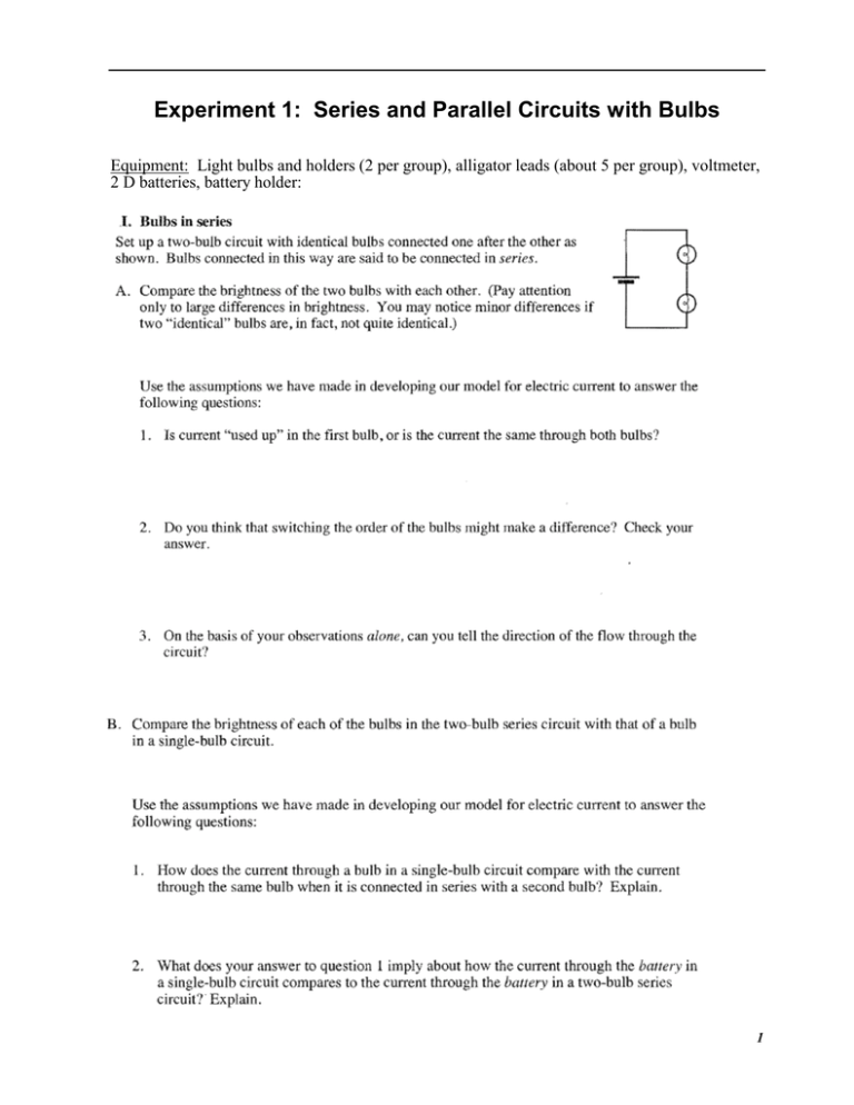
Experiment 1: Series and Parallel Circuits with Bulbs Equipment: Light bulbs and holders (2 per group), alligator leads (about 5 per group), voltmeter, 2 D batteries, battery holder: 1 2 3 4 Experiment 2: Series and Parallel Circuits with Resistors OBJECTIVES To study current flow in series and parallel circuits. To study voltages in series and parallel circuits. ammeter Use Ohm’s law to calculate equivalent resistance of series and parallel circuits. Series Resistors Parallel Resistors MATERIALS two 51 resistors two 68 resistors low-voltage DC power supply connecting wires voltmeter 2 ammeters PROCEDURE Series Circuits Connect the series circuit shown in Figure 2 using the 51 resistors for resistor 1 and resistor 2 instead of the 10 indicated. We are not using a switch in these circuits. Notice the voltmeter is placed in parallel with the resistors to measure the voltage applied to both resistors. The ammeter is placed in series with the other elements of the circuit. The red and black voltage probes are replaced by red and black banana-to-alligator leads. Put the red (positive) lead in the yellow port labeled 10 A. Put the black lead in the com port. Connect the red lead to the positive side of the circuit. Measure the current (I) and total voltage (VTOT). Record the values in the data table. 5 voltmeter ammeter Figure 2 Connect the leads of the voltmeter across resistor 1. Read this voltage (V1). Record this value in the data table. Connect the leads of the voltmeter across resistor 2. Read this voltage (V2). Record this value in the data table. Repeat the procedure with a 68 resistor substituted for resistor 2. 6 Part II Parallel circuits Connect the parallel circuit shown below using 51 resistors for both resistor 1 and resistor 2. As in the previous circuit, the voltmeter is used to measure the voltage applied to both resistors. The red terminal of the ammeter should be toward the + terminal of the power supply. The ammeter is used to measure the total current in the circuit. Figure 3 Measure the total current (I) and total voltage (VTOT). Record the values in the data table. Connect the leads of the voltmeter across resistor 1. Read the voltage (V1) across resistor 1. Record this value in the data table. Connect the leads of the voltmeter across resistor 2. Read the voltage (V2) across resistor 2. Record this value in the data table. Repeat procedure with a 68 resistor substituted for resistor 2. 7 Currents in Series and Parallel circuits Set up the circuit shown below in Figure 4. For this part of the experiment, you will use both multimeters as ammeters. Remember to change leads and put the positive terminal in the 10 A port. Use the 51 resistor for R1 and the 68 resistor for R2. Again, no switch necessary. Figure 4 Measure the current going through each resistor and record your results in the third data table. Repeat for the circuit set up as in Figure 5. Record results Figure 5 DATA TABLE Part I Series Circuits Part I: Series circuits R1 ( ) R2 ( ) 1 51 51 2 51 68 I (A) V1 (V) V2 (V) Req ( ) VTOT (V) 8 Part II: Parallel circuits R1 ( ) R2 ( ) 1 51 51 2 51 68 I (A) V1 (V) V2 (V) Req ( ) VTOT (V) Part III: Currents R1 ( ) R2 ( ) 1 51 51 2 51 68 I1 (A) I2 (A) ANALYSIS (ATTACH TO LAB) 1. Examine the results of Part I. (Series) What is the relationship between the three voltage readings: V1, V2, and VTOT? 2. Using the measurements you have made above and your knowledge of Ohm’s law, calculate the equivalent resistance (Req) of the circuit for each of the three series circuits you tested. 3. Study the equivalent resistance readings for the series circuits. Can you come up with a rule for the equivalent resistance (Req) of a series circuit with two resistors? 4. For each of the three series circuits, compare the experimental results with the resistance calculated using your rule. 5. Using the measurements you have made above and your knowledge of Ohm’s law, calculate the equivalent resistance (Req) of the circuit for each of the three parallel circuits you tested. 6. Study the equivalent resistance readings for the parallel circuits. Devise a rule for the equivalent resistance of a parallel circuit of two resistors. 7. Examine the results of Part II (parallel) What do you notice about the relationship between the three voltage readings V1, V2, and VTOT in parallel circuits. 8. What did you discover about the current flow in a series circuit in Part III? 9. What did you discover about the current flow in a parallel circuit in Part III? 10. If the two measured currents in your parallel circuit were not the same, which resistor had the larger current going through it? Why? 9


