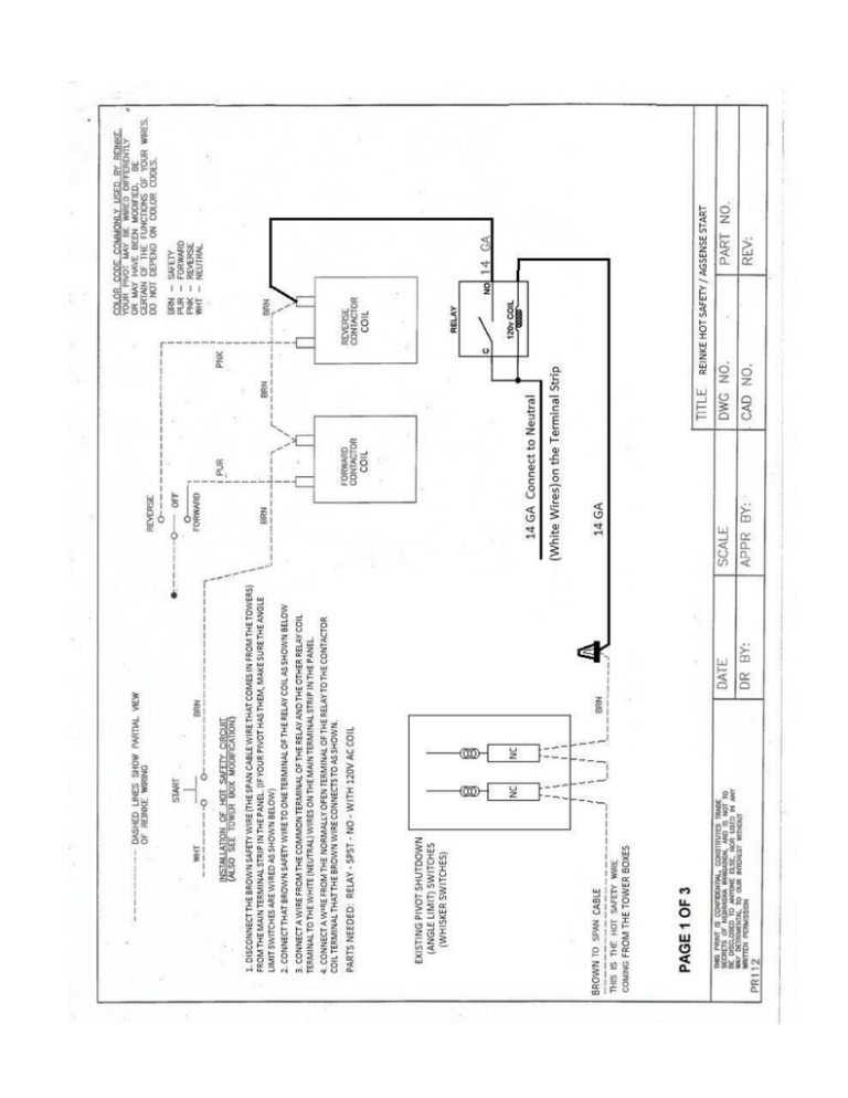
Reinke Hot Safety/Start
advertisement

Using Field Commander to Start Reinke with HOT SAFETY Follow the 3 pages of schematics included to convert the Reinke pivot to a hot safety FIRST. Once that is complete, you must run the pivot and trip the safety switch at one of the towers to ensure the safety system works correctly now that it is re-wired. ONLY AFTER THIS SAFETY TEST PASSES, THEN PROCEED TO STEP 1 OF THE FIELD COMMANDER WIRING BELOW. *NOTE* ON ALL FIELD COMMANDER UNITS – BLACK WIRE WITH RED STRIPE IS NOT USED 1. At the Reinke Control Panel, remove the Reinke Yellow (goes out to the towers) wire from the terminal strip and connect it to 120v at the 120v transformer. (this will give the end gun wire 120v all the time) Also be sure to remove any end gun shutoff switches to make sure the endgun wire always has power. 2. Out at the end tower box, remove the Reinke Yellow (end gun) wire (Span cable side) from the terminal strip in the end tower box and install our Brown wire in its place. 3. Use a wire nut to connect our Black wire to the Reinke Yellow wire that was removed from the terminal strip in step 2. 4. Remove the Reinke brown (safety) wire from the terminal strip in the end tower box (Span Cable Side) and install our Red/Black wire in its place. 5. Use a wire nut to connect our Red wire to the Reinke brown (safety) wire that was removed from the terminal strip in step 4. 6. Install our Brown/Black wire into the terminal strip with the other Reinke Neutral (white) wires. 7. Remove the Reinke orange (percent timer) wire from the terminal strip in the end tower box (Span Cable Side) and install our Blue wire in its place. 8. Use a wire nut to connect our Blue/Black wire to the Reinke orange (percent timer) wire that was removed from the terminal strip in step 7 9. Install our Orange wire into the tower terminal strip with the Reinke Purple wire. (Forward Run) 10. Install our Orange/Black wire into the tower terminal strip with the Reinke Pink wire. (Reverse Run) Steps 9 and 10 must be hooked up for the AgSense unit to work correctly, but that does not mean that Direction Control will work on this pivot! The Direction Control works by applying 120v to the wire opposite of the direction the pivot is currently moving for 10 seconds. – this will not work on all pivots and MUST be tested by the installer before using this feature - Simply test by using a fused jumper wire to connect 120v to the direction wire opposite the direction the pivot is currently moving for 10 seconds. Test this for both directions. If the pivot changes direction and stays moving that direction, then proceed with using this feature. If not, call your AgSense dealer to have the direction control buttons disabled on the website so they are not accidentally used. Power Requirements for these units: DC Powered Unit 7-40V DC: At 12v DC: 1.0A MAX 0.1A - 0.5A during normal operation 120vAC Powered Unit: At 120v AC: 0.25A MAX 0.05A - 0.15A during normal operation The above numbers are the current required for our unit to operate. Below is the current the relays in our box can control: On both AC and DC units, each relay can handle a peak max of 10A, 5A constant (at a max voltage of 120vAC, or 30vDC).


