Installation Instructions Remote Monitor
advertisement

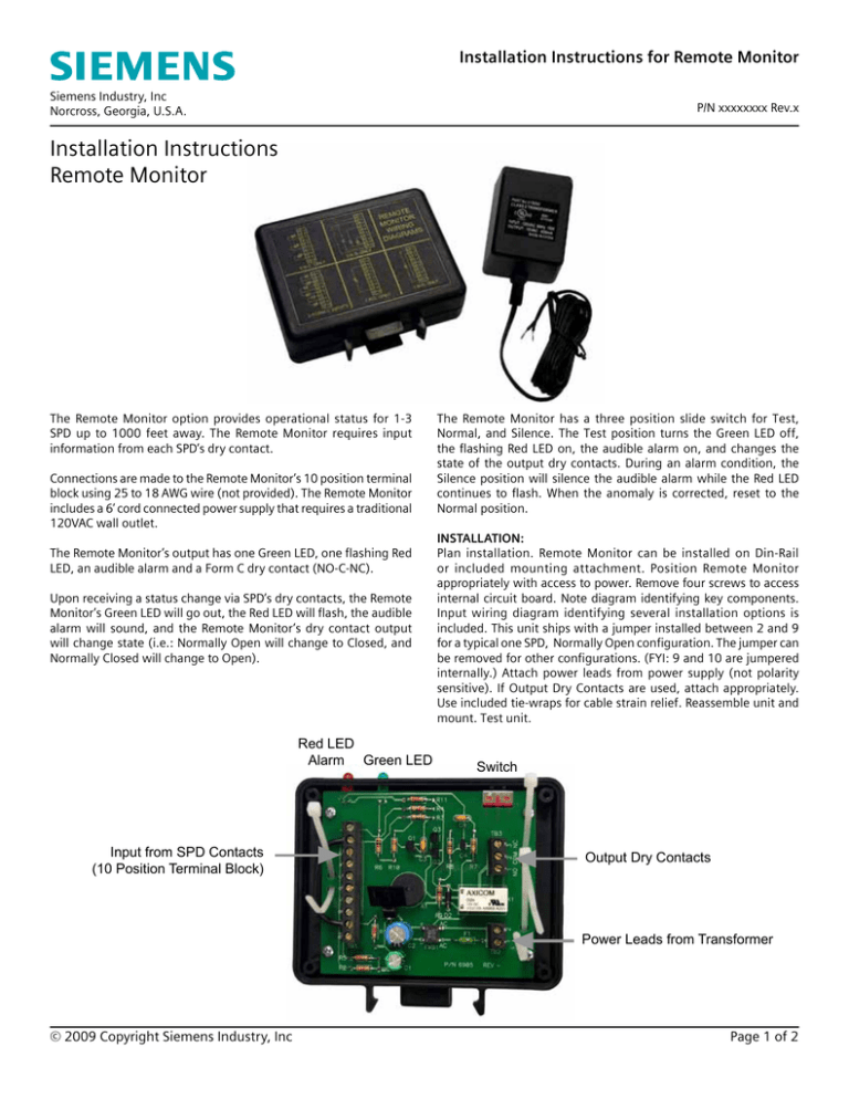
Installation Instructions for Remote Monitor Siemens Industry, Inc Norcross, Georgia, U.S.A. P/N xxxxxxxx Rev.x Installation Instructions Remote Monitor The Remote Monitor option provides operational status for 1-3 SPD up to 1000 feet away. The Remote Monitor requires input information from each SPD’s dry contact. Connections are made to the Remote Monitor’s 10 position terminal block using 25 to 18 AWG wire (not provided). The Remote Monitor includes a 6’ cord connected power supply that requires a traditional 120VAC wall outlet. The Remote Monitor’s output has one Green LED, one flashing Red LED, an audible alarm and a Form C dry contact (NO-C-NC). Upon receiving a status change via SPD’s dry contacts, the Remote Monitor’s Green LED will go out, the Red LED will flash, the audible alarm will sound, and the Remote Monitor’s dry contact output will change state (i.e.: Normally Open will change to Closed, and Normally Closed will change to Open). Red LED Alarm Green LED Input from SPD Contacts (10 Position Terminal Block) The Remote Monitor has a three position slide switch for Test, Normal, and Silence. The Test position turns the Green LED off, the flashing Red LED on, the audible alarm on, and changes the state of the output dry contacts. During an alarm condition, the Silence position will silence the audible alarm while the Red LED continues to flash. When the anomaly is corrected, reset to the Normal position. Installation: Plan installation. Remote Monitor can be installed on Din-Rail or included mounting attachment. Position Remote Monitor appropriately with access to power. Remove four screws to access internal circuit board. Note diagram identifying key components. Input wiring diagram identifying several installation options is included. This unit ships with a jumper installed between 2 and 9 for a typical one SPD, Normally Open configuration. The jumper can be removed for other configurations. (FYI: 9 and 10 are jumpered internally.) Attach power leads from power supply (not polarity sensitive). If Output Dry Contacts are used, attach appropriately. Use included tie-wraps for cable strain relief. Reassemble unit and mount. Test unit. Switch Output Dry Contacts Power Leads from Transformer © 2009 Copyright Siemens Industry, Inc Page 1 of 2 Installation Instructions for Remote Monitor Siemens Industry, Inc Norcross, Georgia, U.S.A. P/N xxxxxxxx Rev.x Remote Monitor Wiring Diagrams Using Normally Closed Contacts Three SPD Two SPD One SPD Using Normally Open Contacts Pinout Diagram for Dry Contacts of SPD Old TVSS DB-9 Style Connector: 1 2 3 4 5 6 7 8 9 1 2 3 4 5 6 7 8 9 Normally Closed Common Normally Open Normally Closed Common Normally Open Connected to Pin 4 Connected to Pin 5 Connected to Pin 6 New SPD Terminal Block Style Connector: DRY CONTACTS Form C Set #1 NO C NC NC C NO Form C Set #2 © 2009 Copyright Siemens Industry, Inc Page 2 of 2 12.09.09 #8176


