Chapter 5 Selected Answers
advertisement
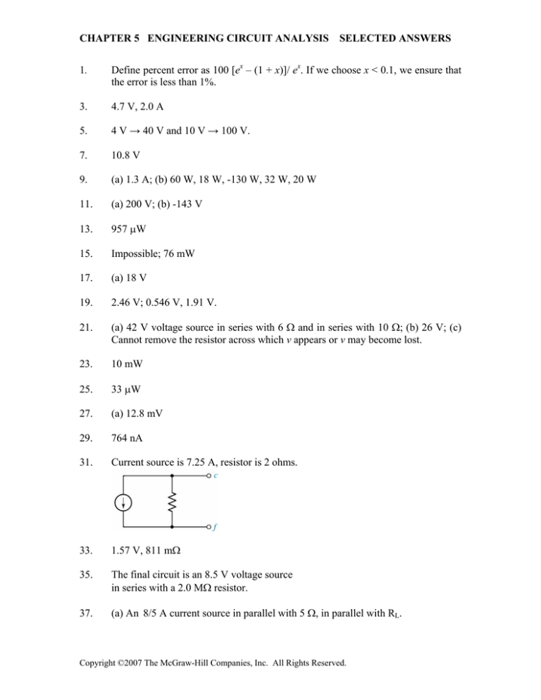
CHAPTER 5 ENGINEERING CIRCUIT ANALYSIS SELECTED ANSWERS 1. Define percent error as 100 [ex – (1 + x)]/ ex. If we choose x < 0.1, we ensure that the error is less than 1%. 3. 4.7 V, 2.0 A 5. 4 V → 40 V and 10 V → 100 V. 7. 10.8 V 9. (a) 1.3 A; (b) 60 W, 18 W, -130 W, 32 W, 20 W 11. (a) 200 V; (b) -143 V 13. 957 μW 15. Impossible; 76 mW 17. (a) 18 V 19. 2.46 V; 0.546 V, 1.91 V. 21. (a) 42 V voltage source in series with 6 Ω and in series with 10 Ω; (b) 26 V; (c) Cannot remove the resistor across which v appears or v may become lost. 23. 10 mW 25. 33 μW 27. (a) 12.8 mV 29. 764 nA 31. Current source is 7.25 A, resistor is 2 ohms. 33. 1.57 V, 811 mΩ 35. The final circuit is an 8.5 V voltage source in series with a 2.0 MΩ resistor. 37. (a) An 8/5 A current source in parallel with 5 Ω, in parallel with RL. Copyright ©2007 The McGraw-Hill Companies, Inc. All Rights Reserved. CHAPTER 5 ENGINEERING CIRCUIT ANALYSIS SELECTED ANSWERS 39. -2 V 41. (a) The Thévenin equivalent is a 9.3 V source in series with a 17 Ω resistor, which is in series with the 5 Ω resistor of interest; (b) 928 mW. 43. (a) 25 Ω; (b) 303 Ω; (c) Increased current leads to increased filament temperature, which results in a higher resistance (as measured). This means the Thévenin equivalent must apply to the specific current of a particular circuit – one model is not suitable for all operating conditions. 45. (a) 6.7 Ω, -300 mA, arrow upwards; (b) 6.7 Ω, -150 mA, arrow upwards. 47. (a) 38.9 V, 178 Ω; (b) 1.96 W. 49. VTH = 0, RTH = 192 Ω. 51. 15 Ω, 15 Ω 53. VTH = 0; The Norton equivalent is 0 A in parallel with 1.3 Ω. 55. VTH (and hence IN) = 0; RTH = RN = 198 mΩ. 57. 2 MΩ 59. VTH = vin Ri ( Ro − AR f ) R1 Ro + Ri Ro + R1 R f + Ri R f + R1 Ri + AR1 Ri ; RTH = Ro (Ri Rf + R1 Rf + R1 Ri) -------------------------------------------------------------Ri Ro + R1 Ro + Ri Rf + R1 Rf + R1 Ri + A R1 Ri. 61. 16 Ω, 6.3 W 63. 65 V, 15 Ω, 70 W 65. (a) 200 V; (b) 125 W; (c) 80 Ω 67. There is no conflict with our derivation concerning maximum power. While a dead short across the battery terminals will indeed result in maximum current draw from the battery, and power is indeed proportional to i2, the power delivered to the load is i2RLOAD = i2(0) = 0 watts. This is the minimum, not the maximum, power that the battery can deliver to a load. 69. Select R1 = RTH = 8 kΩ Copyright ©2007 The McGraw-Hill Companies, Inc. All Rights Reserved. CHAPTER 5 ENGINEERING CIRCUIT ANALYSIS SELECTED ANSWERS 71. 1.2 Ω, 0.54 Ω, 4.9 Ω 73. 9.9 Ω 75. 5.5 V, 1.0 Ω 77. -13 V, 27 Ω 79. Although the network may be simplified, it is not possible to replace it with a three-resistor equivalent. 81. IS(max) = 224 mA 83. 1.4 Ω 85. One possible solution of many: 87. One possible current-limiting scheme is to connect a 9-V battery in series with a resistor Rlimiting and in series with the LED; Rlimiting = 220 Ω. Copyright ©2007 The McGraw-Hill Companies, Inc. All Rights Reserved.


