Engineering Design of a Continuous Duty
advertisement

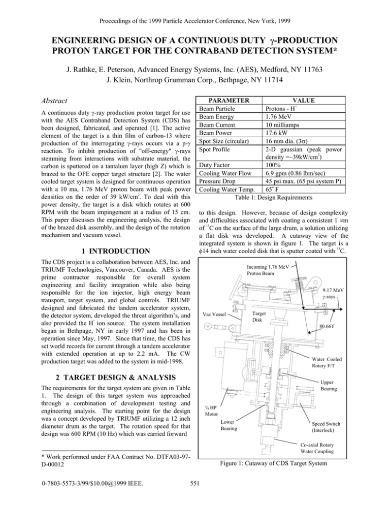
Proceedings of the 1999 Particle Accelerator Conference, New York, 1999 ENGINEERING DESIGN OF A CONTINUOUS DUTY γ-PRODUCTION PROTON TARGET FOR THE CONTRABAND DETECTION SYSTEM* J. Rathke, E. Peterson, Advanced Energy Systems, Inc. (AES), Medford, NY 11763 J. Klein, Northrop Grumman Corp., Bethpage, NY 11714 Abstract A continuous duty γ-ray production proton target for use with the AES Contraband Detection System (CDS) has been designed, fabricated, and operated [1]. The active element of the target is a thin film of carbon-13 where production of the interrogating γ-rays occurs via a p-γ reaction. To inhibit production of "off-energy" γ-rays stemming from interactions with substrate material, the carbon is sputtered on a tantalum layer (high Z) which is brazed to the OFE copper target structure [2]. The water cooled target system is designed for continuous operation with a 10 ma, 1.76 MeV proton beam with peak power 2 densities on the order of 39 kW/cm . To deal with this power density, the target is a disk which rotates at 600 RPM with the beam impingement at a radius of 15 cm. This paper discusses the engineering analysis, the design of the brazed disk assembly, and the design of the rotation mechanism and vacuum vessel. 1 INTRODUCTION PARAMETER Beam Particle Beam Energy Beam Current Beam Power Spot Size (circular) Spot Profile VALUE + Protons - H 1.76 MeV 10 milliamps 17.6 kW 16 mm dia. (3σ) 2-D gaussian (peak power 2 density =~39kW/cm ) Duty Factor 100% Cooling Water Flow 6.9 gpm (0.86 lbm/sec) Pressure Drop 45 psi max. (65 psi system P) o Cooling Water Temp. 65 F Table 1: Design Requirements to this design. However, because of design complexity and difficulties associated with coating a consistent 1 µm 13 of C on the surface of the large drum, a solution utilizing a flat disk was developed. A cutaway view of the integrated system is shown in figure 1. The target is a 13 φ14 inch water cooled disk that is sputter coated with C. The CDS project is a collaboration between AES, Inc. and TRIUMF Technologies, Vancouver, Canada. AES is the prime contractor responsible for overall system engineering and facility integration while also being responsible for the ion injector, high energy beam transport, target system, and global controls. TRIUMF designed and fabricated the tandem accelerator system, the detector system, developed the threat algorithm’s, and also provided the H ion source. The system installation began in Bethpage, NY in early 1997 and has been in operation since May, 1997. Since that time, the CDS has set world records for current through a tandem accelerator with extended operation at up to 2.2 mA. The CW production target was added to the system in mid-1998. Incoming 1.76 MeV Proton Beam 9.17 MeV γ-rays Vac Vessel 80.66° Water Cooled Rotary F/T 2 TARGET DESIGN & ANALYSIS The requirements for the target system are given in Table 1. The design of this target system was approached through a combination of development testing and engineering analysis. The starting point for the design was a concept developed by TRIUMF utilizing a 12 inch diameter drum as the target. The rotation speed for that design was 600 RPM (10 Hz) which was carried forward Target Disk Upper Bearing ¾ HP Motor Lower Bearing Speed Switch (Interlock) Co-axial Rotary Water Coupling * Work performed under FAA Contract No. DTFA03-97D-00012 0-7803-5573-3/99/$10.00@1999 IEEE. 551 Figure 1: Cutaway of CDS Target System Proceedings of the 1999 Particle Accelerator Conference, New York, 1999 13 Development testing showed that for the C coating to survive, it must be deposited on a surface that readily forms carbides and has a good combination of hydrogen solubility and diffusivity. These latter two properties inhibit the formation of hydrogen bubbles. In addition, the substrate also needs to be a high Z material to minimize the production of off-energy γ-rays that would increase the background noise in the detectors. Tantalum was chosen as the substrate and copper coupons with 0.010 inch thick Ta brazed to the surface were successfully tested under simulated CDS beam conditions using the AES pulsed proton beamline. In parallel with the coating development, engineering analyses were conducted in an effort to understand the general conditions of stress, deflection, operating temperature, and pressure drop. The disk structure shown in figure 2 was developed and analysis began using the parameters from table 1. Results from these analyses OFE Cu Face Plate 11.25 deg Sector Model - 20 Node Solid Elements Temperature in Deg F Water Channel 65 deg F at 65 psi 6.9 gpm, ∆p ~20 psi 6.0 in. Figure 3: Steady State Temperatures @ 10mA, 1.76 MeV -.011815 -.010503 -.00919 -.007877 -.006564 -.005251 -.003938 -.002626 -.001313 .956E-12 Commercially Pure Ta Wedges (24) φ14” OFE Cu Back Plate Water Channel 66.039 78.893 91.747 104.602 117.456 130.31 143.164 156.019 168.873 181.727 Mass Balance Pocket Y Deflections in Inches R Criteria: δ +/- 0.020 in. Approximate 1.6 cm 3 σ Beam Width (40% of Channel Width) Figure 4: Y-Deflections at Steady State SST Alignment Pin (2) OFE Cu Hub 0.610 1978 3956 5933 7911 9888 11866 13843 15821 17798 4.5” Conflat Flange Figure 2: Exploded View of Target Disk were evaluated looking for unexpected extremes of thermal stress or deflection. Because of the high rotation speed of the disk, the heat loads were applied as strips of uniform power density around the circumference of the 2 target surface with a central peak value of 257 W/cm . Results for temperature, deflection, and stress are shown in figures 3, 4 and 5 respectively. The peak temperature of 181° F (201° F with fluid heat-up) is reasonable, and the deflections are below half the limit of 0.020 in. (10% of the detector pixel width). Von-Mises stresses of 17,800 psi are high for copper. However, these stresses are dominated by local thermal compressive stress and should result only in local yielding and strain hardening of the copper. Ultimately, cycling may lead to a thermal fatigue “mud-cracking” failure, although copper can generally be expected to perform well under conditions such as these. These results were judged adequate for the first prototype target where limitations on carbon coating lifetime are expected to be the limiting factor. Design changes such as the use of Glidcop (Al2O3 dispersion strengthened copper) will be considered for future designs. Stresses in PSI Values Dominated by Thermal Compression Stresses Figure 5: Von-Mises Stresses at Steady State Worthy of note here is that this scoping analysis was performed before development of the Ta foil substructure. This analysis assumed carbon deposited on a 20 µm layer of gold as the proton stopper. The use of Ta, although non-trivial, was evaluated qualitatively in view of the good performance of coupons in pulsed beam testing. 1-D analysis showed that despite the low conductivity of Ta (14% of Cu), the small thickness of 0.010 in. led to only about a 30° F increase in the steady state surface temperature. This, along with the significantly lower CTE of Ta relative to Cu (more closely matches carbon), led to the conclusion that this material system was appropriate for the first prototype target. 552 Proceedings of the 1999 Particle Accelerator Conference, New York, 1999 3 DETAILED DESIGN Detailed design of the target system and specifically the target disk focused on the techniques for fabricating the water cooled disk with all of the necessary mix of materials and developing a drive system capable of operating for extended periods at 600 to 1000 RPM. A ground-rule at the start was that there be no rotating water seals inside the vacuum. This led directly to the requirement for a rotating high vacuum feedthru capable of these speeds. A two-inch, water cooled ferrofluidic type was chosen. The drive shaft comprises coaxial water tubes for feed and return flow riding on two high capacity bearings which prevent high loads from being transferred to the vacuum feedthru. Figure 6 shows the complete target system installed on the CDS while figure 7 presents an exploded view of the target and vacuum enclosure. also machined to aid in dynamic balancing of the rotating part. This was followed by a CuSil hydrogen braze heat at 1460 F to join the face plate. The face plate was then machined with a groove to accept the 0.010” thick Ta wedges. These wedges were sized to be no bigger than the 2-inch diameter coupons that had been successfully fabricated and tested with beam. As discussed earlier, there is a factor of 2.6 mismatch in thermal expansion coefficient between Ta and Cu so the choice of wafer size was critical to achieving a successful braze. The braze was performed using 0.003 inch thick InCuSil ABA braze alloy. Because of the high affinity of Ta for hydrogen, this braze was performed in high vacuum. The InCuSil ABA (active braze alloy) was chosen because of the relatively low liquidus (1319 F) and the highly aggressive wetting characteristics due to the addition of 1.25% Ti. This characteristic also required that the braze tooling be coated with yttrium oxide paint to prevent bonding. This final brazing step was successfully completed with very little alloy wetting through to the top surface of the Ta. Final machining was performed to “true up” the assembly and clean the Ta in preparation for coating. Figure 8 shows the target disk after sputter coating with 13 C. The black spot on the copper was due to some contamination on the surface probably incurred during the final Ta cleaning process. No contamination was present on the Ta surface as evidenced by good performance in beam testing. Figure 6: CDS CW Target Installation P-Beam Port Alternate p-Beam and γ-ray Ports Cryopump Port IR Camera Port Cryo-Cold Head Port NW500 Flanges 13 Figure 8: Target Disk After C Sputter Coating γ-ray Window 4 SUMMARY Target Disk The CW target was fabricated and has operated successfully at 1.4 mA producing a clean resonant γ-ray beam [3]. Ferrofluidic F/T Figure 7: Exploded View of Target System 5 REFERENCES The target disk itself is a built up brazed structure. Three braze heats in hydrogen atmosphere were required to fabricate the internally cooled structure. A 35/65 Au/Cu heat at 1900 F joined the flange to the hub followed by a PalCuSil-15 heat at 1680 F to join the hub to the back-plate. This heat was followed by machining of the 0.100” deep coolant passages in the back-plate. Because of the asymmetry of the passages, a pocket was [1] Sredniawski, et al; "A Contraband Detection System Proof-ofPrinciple Device Using Electrostatic Acceleration, "Proceedings of the XVIII International Linear Accelerator Conference, p. 444-446, 26-30 August, 1996; Geneva, Switzerland. [2] Melnychuk, et al, "Development of a Thin Film 9.17 MeV Gamma Production Target for the Contraband Detection System", These Proceedings. [3] Melnychuk, et al, "Operating Characteristics of a High Current Electrostatic Accelerator for a Contraband Detection System,” These Proceedings. 553


