axicom composite insulators htv
advertisement
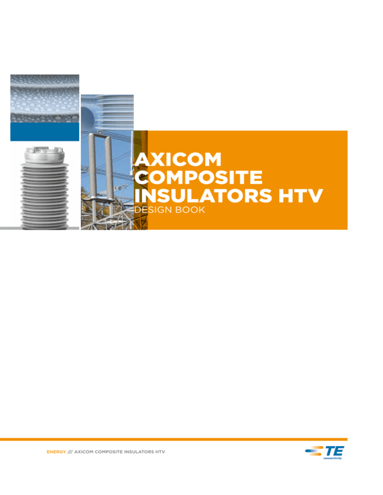
AXICOM COMPOSITE INSULATORS HTV DESIGN BOOK ENERGY /// AXICOM COMPOSITE INSULATORS HTV 2 Table of contents I Design Book Presentation 3 How to design your own AXICOM Hollow Insulator HTV ? 6 Design Guide Step 1 6 Design Guide Step 2 7 Design Guide Step 3 8 Design Guide Step 4 9 Standards Specification Sheet for AXICOM Composite Insulators ENERGY /// AXICOM COMPOSITE INSULATORS HTV 10 11 Design Book 3 Presentation Since more than 25 years AXICOM Composite Insulators from TE Connectivity have been in service worldwide as important components of high voltage apparatuses, modern circuit breakers, instrument transformers, cable terminations, bushings, station post insulators and other components in high voltage substations. Utilize this advanced technology for voltage up to 1100 kV AC and 800 kV DC. Far more than 250.000 insulators were produced in our plant in Wohlen, Switzerland. Excellent reliability, zero maintenance and great safety bring tremendous benefits to our customers worldwide. HV equipment manufacturers capitalize on their low weight, short lead-times, easy handling and support of development for new and more economical HV solutions. All our experience is implemented in our new state of the art factory located in Kunshan, China. According to the expanding requirements worldwide the factory deals with highly developed technical equipment and engineering tools. The silicone material in Kunshan was changed to HTV, this helps us to increase our competitiveness, and in the same time remain our highest quality of insulators. At Kunshan factory we have a full range of test equipments for testing of design criteria, e.g. mechanical loads, tightness testing, burst pressure and electrical behaviour according to IEC 61462 and IEC 62217. With regard to this, the HV Test laboratory can test up to 1200 kV AC and 1800 kV impulse voltage. This new factory will increase our flexibility on the market to be able to meet very different requirements from our customers. ENERGY /// AXICOM COMPOSITE INSULATORS HTV 4 Design Book How to design your own AXICOM Hollow Insulator HTV ? How to design your own AXICOM Hollow Insulator HTV ? The following pages give you an overview of our insulators and the ability to design your own composite hollow core insulator for your electrical apparatus. On the basis of a few inputs, all requirements can be fixed and TE can start to design. Step 1 Select the needed inner diameter of the insulator Step 2 Select the mechanical requirements, e.g. MSP, MML, filling medium etc. for the needed tube material Step 3 Select dimensions like creepage and arcing distance, shed form, overall length etc. Step 4 Select the required flanges ENERGY /// AXICOM COMPOSITE INSULATORS HTV How to design your own AXICOM Hollow Insulator HTV ? Design Book 5 Step 1 Step 1 Inner diameter of an insulator Cylindrical The tube of a composite insulator is an internal insulating part and is designed to ensure the mechanical characteristics. The tube is generally manufactured of resin-impregnated glass fibres. The impregnation resin is an epoxy resin with properties, which adapts to the requirements of high voltage and outdoor applications. The endless fibres are arranged in different manners to achieve a specified mechanical strength and guarantee the lowest deflection under cantilever load. Inner Diameter ID (mm) Outer Diameter OD (mm) 130 142 154 166 198 206 248 257 300 312 358 374 486 510 586 610 The different diameters fulfil all requirements. With both cylindrical and conical designs, insulators of up to 12 m in length can be produced. On the left, you see an overview of the complete range of tubes. Other inner diameters are available if needed. Without protection layer against SF With protection layer against SF MML MSP Stiffness A2312 A2313 * *** * A2314 A2315 ** ** ** A2316 A2317 ** * *** A2318 A2319 *** * *** TE Connectivity established four standard Cevolit tube systems, which are selectable in Step 2. ENERGY /// AXICOM COMPOSITE INSULATORS HTV Design Book 6 How to design your own AXICOM Hollow Insulator HTV ? Design Book Step 2 Step 2 Selection of tube material TE Connectivity develops different tube materials to fulfil all required mechanical strengths. Additionally, a protection layer against SF6 can be implemented. The wet winding tubes with endless fibres are produced under strict strength quality standards and control. Special tube materials can be produced on request. The following overview shows some typical references. Inner criteria: • Filling medium • Pressurized Y/N? • Bending Load Cevolit A2312/2313 Type max. mechanical load, MML [kNm] max. service pressure, MSP [Mpa] Cevolit A2314/2315 max. Specific deflection, mechanical 3 [mm/kN/m ] load, MML [kNm] max. service pressure, MSP [Mpa] Cevolit A2316/2317 Specific max. deflection, mechanical 3 [mm/kN/m ] load, MML [kNm] max. service pressure, MSP [Mpa] Cevolit A2318/2319 Specific max. deflection, mechanical 3 [mm/kN/m ] load, MML [kNm] max. service pressure, MSP [Mpa] Specific deflection, [mm/kN/m3] 142 2,4 2,8 4,3 4,1 2,3 2,9 5,4 1,6 2,3 5,6 1,2 2,1 166 3,4 2,4 2,6 5,8 2,0 1,8 7,1 1,3 1,4 7,3 1,0 1,2 206 3,7 1,2 1,9 6,2 1,0 1,3 7,8 0,7 1,1 8,1 0,5 0,91 257 6,6 1,1 0,88 11 0,9 0,61 14,5 0,6 0,48 16,6 0,5 0,41 312 12,9 1,2 0,37 21,6 1,0 0,25 24,6 0,7 0,2 25,6 0,5 0,17 374 24,7 1,4 0,16 39,9 1,1 0,11 42,5 0,7 0,09 44,1 0,6 0,07 510 68,4 1,5 0,04 93,2 1,3 0,03 98,8 0,8 0,02 102,5 0,6 0,02 610 99,1 1,3 0,02 150,9 1,0 0,02 160,8 0,7 0,01 167,1 0,5 0,01 Note ENERGY /// AXICOM COMPOSITE INSULATORS HTV deflection [mm] = specific deflection x bending load [kN] x (insulator length [m])3 How to design your own AXICOM Hollow Insulator HTV ? Design Book 7 Step 3 Step 3 Shed profile With regard to the outer design, different components are important for the overall dimensions of an insulator: Design Book • Arcing distance • Creepage distance • Pollution class • Shed form • Service temperature Ø ≤ 257 mm Ø ≤ 312 mm AXICOM China Hollow Core Insulators are moulded directly on the tube with different shed forms. To fulfil the specified creepage distance, the shed forms were designed and optimized according to IEC 60815-3. Alternating sheds Type Outer Ø Insulator, E (mm) Shed spasing, T (mm) Alternating shed step, Tk (mm) Creepage factor, Cv (mm) Top interval to flange, O (mm) Bottom interval to flange, U (mm) 142 256 50 23 207 55 55 166 280 50 23 207 55 55 206 320 50 23 207 55 55 257 371 50 23 207 55 55 312 452 65 30 277 55 55 374 514 65 30 277 55 55 510 650 65 30 277 55 55 610 750 65 30 277 55 55 Note Number of sheds = n Arching distance alternating sheds SW = O + (n - 1) x T + Tk + U Creepage distance L = O - T + Tk + (n x Cv) + U ENERGY /// AXICOM COMPOSITE INSULATORS HTV 8 How to design your own AXICOM Hollow Insulator HTV ? Design Book Step 4 Step 4 Flange Design A great range of standard flanges is available at TE Connectivity. The following overview shows you the capability of aluminium alloy flanges. The end-flanges are part of the insulator and they are assembled with the tube using AXICOM China´s special gluing technology. This is done to transmit the mechanical loads and seal the adjacent structure. Standard Flanges Data Diameter 142 166 206 257 312 Pos. FA (mm) FB (mm) ØF5 (mm) ØFT (mm) n x Ød (mm) Pos. 21 55 8 205 185 12 x Ø11 Pos. 22 65 12 205 185 12 x Ø11 Pos. 23 85 12 205 185 12 x Ø11 Pos. 24 110 15 205 185 12 x Ø11 Pos. 31 55 8 232 212 16 x Ø11 Pos. 32 65 10 232 212 16 x Ø11 Pos. 33 85 12 240 220 16 x Ø11 Pos. 34 110 15 240 220 16 x Ø11 Pos. 41 55 8 286 260 16 x Ø11 Pos. 42 65 10 286 260 16 x Ø11 Pos. 43 85 12 286 260 16 x Ø11 Pos. 44 110 15 286 260 16 x Ø11 Pos. 51 65 10 344 314 16 x Ø11 Pos. 52 85 12 344 314 16 x Ø11 Pos. 53 110 15 344 314 16 x Ø13.5 Pos. 54 150 20 344 314 16 x Ø13.5 Pos. 61 65 10 380 360 24 x Ø11 Pos. 62 85 12 380 360 24 x Ø11 Pos. 63 110 15 400 370 24 x Ø13.5 Pos. 64 150 20 410 380 24 x Ø13.5 Pos. 71 65 10 442 422 24 x Ø11 Pos. 72 85 12 442 422 24 x Ø11 Pos. 73 110 15 462 432 24 x Ø13.5 Pos. 74 130 15 462 432 24 x Ø13.5 Pos. 75 160 20 462 435 24 x Ø13.5 Pos. 81 85 15 598 568 24 x Ø13.5 Pos. 82 110 15 598 568 30 x Ø13.5 Pos. 83 130 20 602 572 30 x Ø13.5 Pos. 84 160 20 602 572 30 x Ø13.5 Pos. 91 145 30 715 680 32 x Ø13.5 374 510 610 Additionally to these standard flanges, we are able to produce any kind of metal flanges that are required. There are different kinds of production possibilities: • Die cast • Sand cast • Solid material • Forged flanges • Varnished flanges • Anodized flanges All flanges feature a high quality standard to realize a high performance and corrosion resistance. Please ask for more details. ENERGY /// AXICOM COMPOSITE INSULATORS HTV Design Book 9 Standards Standards Design and Type tests according to IEC 61462 Design Book Design tests 7.0 Type tests 8.0 Tests on interfaces and connections of end fittings 7.2 Reference dry power frequency flashover test 7.2.2 Thermalmechanical pre-stressing test 7.2.3 Water immersion pre-stressing test 7.2.4 Verification tests 7.2.5 Visual examination 7.2.5.1 Steep-front impulse voltage test 7.2.5.2 Dry power frequency voltage test 7.2.5.3 Internal pressure test 7.2.5.4 Tests on shed and housing material 7.3 Hardness test 7.3.1 Mechanical type tests according to IEC 61642 Bending Tube in phase 1.0 x MML Reversible elastic 1.5 x MML, residual strain ≤ ±5% Reversible elastic 2.5 x MML, no visible damages Irreversible plastic SML ≥ 2.5 x MML, breaking value Irreversible plastic Internal pressure Tube in phase 1.0 x MSP Reversible elastic 2.0 x MSP, residual strain ≤ ±5% Reversible elastic 4.0 x MSP, no visible damages Irreversible plastic SIP ≥ 4.0 x MSP, breaking value Irreversible plastic Definitions MML Maximum Mechancial Load which is the design load for the equipment manufacturer SML Specified Mechanical Load, a load specified by the manufacturer that is used MSP Maximum Service Pressure which is the design pressure for the equipment manufacturer SIP Specified Internal Pressure, an internal pressure specified by the manufacturer ENERGY /// AXICOM COMPOSITE INSULATORS HTV Accelerated weathering test 7.3.2 Tracking and erosion test 7.3.3 Flammability test 7.3.4 Tests on tube material 7.4 Dye penetration test 7.4.1 Water diffusion test 7.4.2 Internal pressure test 8.4 Bending test 8.5 Design Book Specification Sheet for AXICOM Composite Insulators Specification Sheet for AXICOM Composite Insulators Customer Contact person Apparatus Quantity per year / batch size Req. unit Outer Criteria Step 3 Inner Criteria Step 1 and 2 Inner tube diameter in mm Tube material SF6 Oil other. Cevolit Pressurized Yes Maximum Service Pressure (MSP) MPa. Maximum mechanical load (MML) kN Specified mechanical load (SML) kN Deflection@MML mm Nominal Service Voltage kV BIL kV Pollution level according to IEC 60815 / Creepage distance mm Service temperature range °C min. arcing distance mm min. creepage length mm Insulator length mm No Top Bottom Top Bottom Standard designation Special Flanges Bolt Cicle Diameter (BCD) mm Outer Flange Diameter mm Number and size of holes mm Remarks Flanges Step 4 Customer's Needs mm Insulating medium Standard Flanges Contact details customer (first name, last name, company, email addres, phone number). Contact 10 ENERGY /// AXICOM COMPOSITE INSULATORS HTV Design Book Notes 11 Notes Design Book ENERGY /// AXICOM COMPOSITE INSULATORS HTV TE Connectivity (NYSE: TEL) is a $14 billion global technology leader. Our connectivity and sensor solutions are essential in today’s increasingly connected world. We collaborate with engineers to transform their concepts into creations – redefining what’s possible using intelligent, efficient and high-performing TE products and solutions proven in harsh environments. Our 80,000 people, including 7,500 design engineers, partner with customers in over 150 countries across a wide range of industries. We believe EVERY CONNECTION COUNTS - www.TE.com •Mining •Substations • Nuclear power plants • Transmission lines •OEMs • Underground distribution • Overhead distribution •Windfarms • Petrochemical plants •Solar •Railways •Hydro-electric • Street lighting WHEREVER ELECTRICITY FLOWS, YOU’LL FIND TE ENERGY te.com/energy FOR MORE INFORMATION: EMEA and Americas Market Asia Market Plant AXICOM Wohlen TE Connectivity (Shanghai) Co., Ltd. Industriestrasse 14 5610 Wohlen QinJiang Road 307, Shanghai Switzerland 200233 China Tel: +41 56 6188700 Tel: +86 021 61 067 000 Fax:+41 56 6188701 Fax:+86 021 54 270 322 productsupport-axicom@te.com www.te.com.cn/zh/industries/energy.html te.com/energy ® 2014 TE Connectivity Ltd. family of companies. All Rights Reserved. 1773451-7 EPP-2367-10/14 AXICOM, Raychem, TE Connectivity and the TE connectivity (logo) are trademarks of the TE Connectivity Ltd. family of companies. Other logos, product and Company names mentioned herein may be trademarks of their respective owners. While TE has made every reasonable effort to ensure the accuracy of the information in this brochure, TE does not guarantee that it is error-free, nor does TE make any other representation, warranty or guarantee that the information is accurate, correct, reliable or current. TE reserves the right to make any adjustments to the information contained herein at any time without notice. TE expressly disclaims all implied warranties regarding the information contained herein, including, but not limited to, any implied warranties of merchantability or fitness for a particular purpose. The dimensions in this brochure are for reference purposes only and are subject to change without notice. Specifications are subject to change without notice. Consult TE for the latest dimensions and design specifications. ENERGY /// AXICOM COMPOSITE INSULATORS HTV
