Series Reactive RC Circuits
advertisement

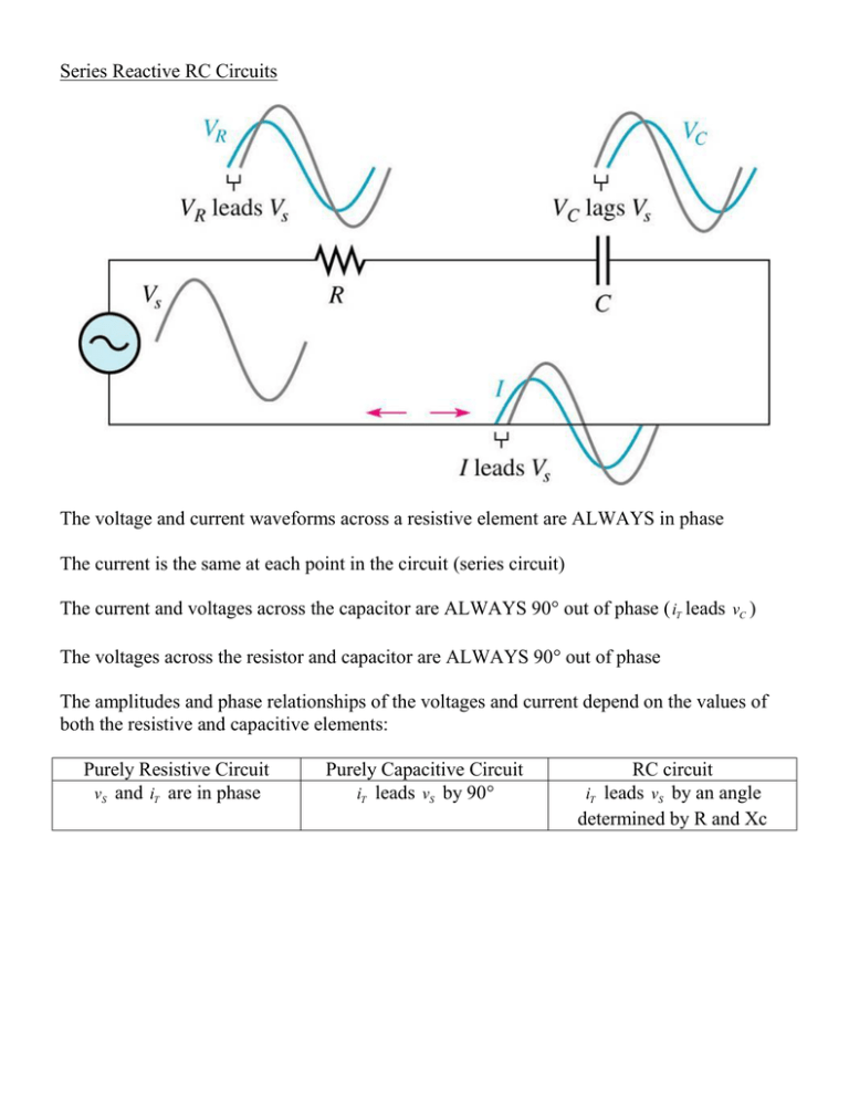
Series Reactive RC Circuits The voltage and current waveforms across a resistive element are ALWAYS in phase The current is the same at each point in the circuit (series circuit) The current and voltages across the capacitor are ALWAYS 90° out of phase ( iT leads vC ) The voltages across the resistor and capacitor are ALWAYS 90° out of phase The amplitudes and phase relationships of the voltages and current depend on the values of both the resistive and capacitive elements: Purely Resistive Circuit vS and iT are in phase Purely Capacitive Circuit iT leads vS by 90° RC circuit iT leads vS by an angle determined by R and Xc Impedance (Z) Impedance in an AC circuit is the total opposition to the flow of current, and is given units of ohms: Z R2 X C 2 The phase angle associated with a reactive RC circuit may be determined by the relative magnitudes of the resistive and reactive elements: XC R tan 1 Note: Impedance always has a phase angle associated with it Complex Representation Phasor Representation Ohm’s Law in Series Reactive RC circuits Since the voltage and current in a series RC circuit are out of phase, the phase angles MUST be taken into account when solving these circuits. This is most easily accomplished by representing phasor quantities in polar form. Substituting impedance (Z) for resistance gives the following three equivalent forms of Ohm’s Law for reactive circuits: V IZ I V Z Z V I where V, I and Z are phasor quantities (with both magnitude and phase angles) Example: If the current in the following circuit is given as I 0.20mA , determine the source voltage and draw a phasor diagram showing the relation between source voltage and current. KVL in Series Reactive RC Circuits Since the voltages across the resistive and capacitive elements are NOT in phase, their magnitudes CANNOT simply be added to find the total source voltage – they must always be added as phasor quantities (magnitude and associated phase angle). VS VR jVC V 2 2 VS VR VC tan 1 C VR The effects of frequency on a series reactive RC circuit Remember that Capacitive Reactance is inversely proportional to frequency. Therefore, as the frequency is increased, the capacitive reactance and therefore the total impedance will decrease. The opposite is true if frequency is decreased – the capacitive reactance and impedance both increase. The following figure illustrates the effect of frequency on total circuit current and voltage across each component: Since the phase angle associated with an AC RC circuit is determined by the ratio of Xc/R, it follows that it is also inversely proportional to frequency: Example: determine the current I, and the voltages across R and C in the following circuit. Draw the phasor diagram showing all four components:
