GBL Series AFT/AI/A5 Reflector Kit
advertisement
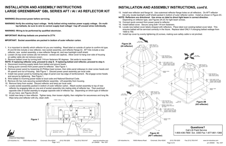
INSTALLATION AND ASSEMBLY INSTRUCTIONS LARGE GREENBRIAR® GBL SERIES AFT / AI / A5 REFLECTOR KIT WARNING:Disconnect power before servicing. WARNING:Verify the existing input voltage. Verify ballast wiring matches power supply voltage. On multitap ballasts, be sure to wire to correct supply lead voltage! Cap off unused wires individually. WARNING: Wiring to be performed by qualified electrician. IMPORTANT: Multi-tap ballasts are prewired to 277V. INSTALLATION AND ASSEMBLY INSTRUCTIONS, cont'd. 13. Install new reflector and flange kit. Use outermost reflector flange holes on all reflectors. On AFT reflector kits only, locate backlight cutoff shield packed in bottom of outer reflector carton. Install as shown in Figure 2C. NOTE: Reflectors are directional. Use arrow on label to direct light beam in correct direction. Depending on reflector type, see Figures 2A-2C for light beam arrows. 14. Connect quick connect from power panel to reflector. 15. Install ballast cover. Secure using both 1/4-turn fasteners. 16. Locate new ballast cover labels shipped with reflectors. Place label over existing ballast cover label. This ensures ballast will be serviced correctly in the future. Replace label ONLY if changing ballast wattage from 1000 to 750. 17. Install top cover by evenly tightening (4) screws, making sure safety cable is not pinched. MPORTANT: Socket assemblies are packed in bottom of outer reflector carton. 1. It is important to identify which reflector kit you are installing. Read label on outside of carton to confirm kit type. AI and A5 kits include a new reflector, new socket assembly, and reflector flange kit. AFT kits include a new reflector, new socket assembly, a new reflector flange kit, and new backlight cutoff shield. 2. Loosen (4) top cover screws (do not remove - screws are captive). Allow cover to hang over side of housing on safety cable (do not remove cover). 3. Remove ballast cover by turning both 1/4-turn fasteners 90 degrees. Set aside to reuse later. NOTE: If replacing reflector only, proceed to step 9. If replacing ballast and reflector, proceed to step 4. 4. Disconnect incoming supply leads from ballast and ground leads. 5. Unplug quick connect from power panel to reflector. See Figure 1. 6. Remove power panel by loosening (2) Phillips-head screws, then slide panel sideways to clear screw heads and lift upward and out of housing. See Figure 1. Discard power panel assembly per local code. 7. Install new power panel by hooking top edge of panel over top edge of reinforcement. Re-engage screw heads and secure by tightening. See Figure 1. 8. Wire ballast to incoming power leads to local code and National Electrical Code. 9. Remove (5) hex nuts securing socket/reflector assembly. Lift assembly from housing. 10. Remove lamp from socket. Discard reflector and lamp per local code. 11. Locate socket assembly packed in bottom of outer reflector carton. Attach socket assembly to top of new reflector by engaging tabs on one end of socket assembly into mating slots of reflector top. Then push/pull opposite side of socket asembly to engage opposite side of reflector top. Depending on which type of reflector kit you have, see Figures 2A-2C. 12. Install new lamp in new reflector. Tighten lamp, then loosen slightly, then retighten for secureness and long life. Wipe lamp and reflector with dry, clean cloth. Figure 2A (AI reflector) Figure 2B (A5 reflector) Figure 1 Questions? Figure 2C (AFT reflector) LSI Industries Inc. 10000 Alliance Road Cincinnati, Ohio 45242 (513) 793-3200 Page 1 of 2 Fax (513) 793-0147 www.lsi-industries.com p/n 254628 Rev. 5/07 LSI Industries Inc. 10000 Alliance Road Cincinnati, Ohio 45242 Call LSI Field Service 1-800-436-7800 Ext. 3300 Fax 1-877-861-1368 (513) 793-3200 Page 2 of 2 Fax (513) 793-0147 www.lsi-industries.com p/n 254628 Rev. 5/07
