Torque and Rotary Motion 3.0
advertisement
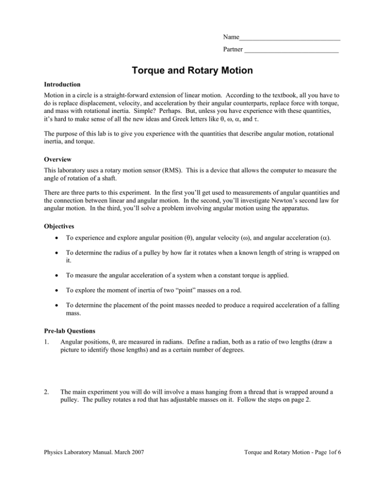
Name______________________________ Partner ____________________________ Torque and Rotary Motion Introduction Motion in a circle is a straight-forward extension of linear motion. According to the textbook, all you have to do is replace displacement, velocity, and acceleration by their angular counterparts, replace force with torque, and mass with rotational inertia. Simple? Perhaps. But, unless you have experience with these quantities, it’s hard to make sense of all the new ideas and Greek letters like θ, ω, α, and τ. The purpose of this lab is to give you experience with the quantities that describe angular motion, rotational inertia, and torque. Overview This laboratory uses a rotary motion sensor (RMS). This is a device that allows the computer to measure the angle of rotation of a shaft. There are three parts to this experiment. In the first you’ll get used to measurements of angular quantities and the connection between linear and angular motion. In the second, you’ll investigate Newton’s second law for angular motion. In the third, you’ll solve a problem involving angular motion using the apparatus. Objectives • To experience and explore angular position (θ), angular velocity (ω), and angular acceleration (α). • To determine the radius of a pulley by how far it rotates when a known length of string is wrapped on it. • To measure the angular acceleration of a system when a constant torque is applied. • To explore the moment of inertia of two “point” masses on a rod. • To determine the placement of the point masses needed to produce a required acceleration of a falling mass. Pre-lab Questions 1. Angular positions, θ, are measured in radians. Define a radian, both as a ratio of two lengths (draw a picture to identify those lengths) and as a certain number of degrees. 2. The main experiment you will do will involve a mass hanging from a thread that is wrapped around a pulley. The pulley rotates a rod that has adjustable masses on it. Follow the steps on page 2. Physics Laboratory Manual. March 2007 Torque and Rotary Motion - Page 1of 6 a. At the right is a drawing of the essential features of the rotating and moving portions of the RMS system. Define a coordinate system and draw the free-body diagram for the mass, m, hanging from the thread: G G b. Write Newton’s second law, F = m a , for the mass on the thread. Solve the equation to find the tension on the thread: c. Draw a torque diagram (about the axis of rotation) for the pulley with the thread around it. You should show the force, the distance between the axis of rotation and the point at which the force is applied, and the angle between the two. Show the connection between the torque (τ), the tension in the thread (T) and the radius (r) of the pulley. d. Write Newton’s second law, e. Write the (constraint) equation relating α (the angular acceleration of the rotating system) to a (the linear acceleration of the mass and thread) and r (the radius of the pulley). G G τ = I α , for the rotation of the pulley. End of Pre-lab Questions. Part 1: Angular Measurements Equipment • Rotary motion sensor (RMS) • Three-step pulley, rod, two brass masses, clamp-on pulley • Protractor, meter stick, vernier caliper, thread • File Torque Introduction Here’s a brief review of ways to measure angular motion. First, we’ll review the definitions of linear and angular measure: Physics Laboratory Manual. March 2007 Torque and Rotary Motion - Page 2of 6 Quantity Linear motion Angular motion Position x (m) θ (rad) (theta) Velocity v (m/s) ω (rad/s) (omega) Acceleration a (m/s2) α (rad/s2) (alpha) Suppose that you wrap a string around a pulley that has a radius r and that you pull the string. The pulley turns through an angle θ. A location on the edge of the pulley will move through a distance, s, the arc length is given by s = rθ. If the string didn’t slip, it moved a distance x = s. Therefore you can relate the angular motion of the pulley and the linear motion of the end of the string. Fill in the two “Compute” columns of the table below with an equation that relates the computed quantity to the measured quantity and the size of the pulley. Quantity Measure Compute Measure Compute Position x θ= θ x= Velocity v ω= ω v= Acceleration a α= α a= Making angular measurements Look at the Rotary Motion Sensor (RMS). There should be a thread wrapped around the pulley. Make sure that the end of the thread is secure to the pulley so that it won’t get loose and tangled when you rotate the rod. Move the brass pieces until they are at the ends of the rod and tighten the thumbscrews. Radians and revolutions Start LoggerPro and open the file Torque. Gently rotate the rod on the RMS and watch the angular position change on the screen. To get a feeling for the size of a radian, record the following measurements given by the program. 1. Rotate the rod 1 complete revolution in the clockwise direction. What is the change in angular position recorded by the RMS? θ = ______________ rad. Is the sign consistent with usual sign convention? Remember in physics positive signs are associated with counterclockwise rotations. 2. Rotate the rod 5 complete revolutions in the counter-clockwise direction. What is the change in angular position recorded by the RMS? θ = ______________ rad. 3. Hold the protractor above the rod and rotate it until the RMS records a change of 1 radian. Find the angle as measured on the protractor. 1 rad = ________ deg. 4. Start the rod spinning slowly. Start collecting data and use your watch (if it has a second hand) or the wall clock to find the number of seconds needed for the rod to complete two revolutions. Time for two revolutions = _______ s. Compute the average angular velocity of the rod ω = ∆θ/∆t = (________ rad)/(______ s). 5. Use the program to find the average angular velocity from the angle-time graph. Select the portion of the graph to fit. Click on the Fits icon, Physics Laboratory Manual. March 2007 , and choose Linear. The slope (m) is the average angular Torque and Rotary Motion - Page 3of 6 velocity. ωavg = ________ rad/s. Compare this number with the angular velocity you calculated above. Make sure the two are either the same or that you can explain the difference. Angular and linear motion Practice getting the thread to wrap around one of the three steps on the pulley. You’ll probably need either a thin finger or a pencil to get it on the step you desire. If the thread breaks, your instructor will show you how to replace it. You’ll next use the relationship between angular and linear measure in the table above to calculate the radius of each step of the pulley. You will pull the thread a measured distance and use the RMS to measure the angular displacement of the rod. Note that to make accurate measurements, you’ll have to keep the thread taut at all times. When you have finished, use the vernier caliper to measure the diameter of the steps, and then find the “measured” radius, r′. The “diameter of the steps” is not just the radius of the empty pulley but the radius of the pulley with the thread wound around it. Pulley Step Thread length x (m) Angle θ (rad) Calculated radius r (m) Measured diameter d (m) Measured radius r′ (m) Percent difference with comments 1 2 3 Questions 1a. If you measure the pulley turning at a constant angular velocity ω = 1.25 rad/s and the thread were wound around step 2, how fast would the end of the thread be moving? v = _______________ . 1b. How long would it take the end of the thread to move 0.40 m? t = ______________ 2a. If the angular acceleration of the pulley were α = 0.50 rad/s2 and the thread were wound around step 2, what would be the linear acceleration of the end of the thread? a = _____________ m/s2. 2b. If the pulley started from rest, how far would the end of the thread move in 15.0 s? _____________. Part 2: Torque and Angular Acceleration Equipment • • • • Rotary motion sensor (RMS) Three-step pulley, rod, clamp-on pulley Meter stick, 50-g mass, thread File Torque a. Angular acceleration Wrap the thread around the step 2 of the three-step pulley. The thread should be wrapped in the direction so that when you pull on it, the pulley rotates in the counter-clockwise (positive) direction. Feed the thread over the pulley clamped on the RMS, and attach a 50-g mass to the end of the thread. Release the mass from rest and see what happens. Measure the angular acceleration by finding the slope of the angular velocity as a function of time. Using the mouse “grab” some angular velocity data in the region of the curve where the Physics Laboratory Manual. March 2007 Torque and Rotary Motion - Page 4of 6 slope is relatively smooth. Click on the Fits icon, , and choose Linear. The slope (m) is the average angular acceleration. Label this graph with the title “from rest” and print it out with the slope data included. Now redo the above with the initial condition that the rod is already moving when the data collection begins. So the rod is moving counterclockwise as the mass falls. Again measure the angular acceleration by fitting the data on the angular velocity curve to a straight line. Label this graph with the title “moving in the + direction” and print it out with the slope data included. Once again, redo the above with the initial condition that the rod has been set in clockwise motion with the hanging mass moving upward. Label this graph with the title “moving in the – direction” and print it out with the slope data included. Report your results for the three cases (from rest, moving in the + direction, moving in the – direction) below. α = _________________rad/s2 α = _________________rad/s2 α = _________________rad/s2 Do the three angular accelerations agree? ________ Within what percent? ___________ . Question 1. Why should we even expect the three accelerations reported above to be equal?____________________ ______________________________________________________________________________________ ______________________________________________________________________________________. b. Rotational Inertia Measure the angular acceleration (α) for four different hanging masses (m). You should put both brass pieces at the end of the rod and measure the distance between the center of the rod and the center of the set screw on the brass piece (R). Keep the thread wrapped around step 2. Report the values of m and α in the table below. When you are done remove the brass pieces and measure their mass (M). r(step 2) = __________m. m(kg) R =____________m. α (rad/s2) a = αr M = __________kg. T = m(g – a) τ = Tr Plot τ (on the y-axis) as a function of α using Graphical Analysis for Windows. Fit a regression line through the data and report the slope below. Print out a copy of the graph with the regression line reported. The slope of the graph is the rotational inertia, I, of the entire pulley system. Calculate the rotational inertia (2 MR2) of the two brass pieces, then calculate Io, the rotational inertia of the rod, “guts” of the RMS, pulleys, etc. Slope = ____________kg*m2. 2 MR2 = ______________kg*m2. Io =_____________kg*m2. Question 1. The analysis in this experiment ignored friction. But there is friction here though it is not very large. So is your measured slope (or I) a bit too big or a bit too small?_____________________________. Physics Laboratory Manual. March 2007 Torque and Rotary Motion - Page 5of 6 Explanation:___________________________________________________________________. Part 3: A Final Problem to Solve Now that you have found the rotation inertia, Io, of the “guts” of the system let us use this to make one final prediction. First identify the smallest mass from the table above and then identify the largest acceleration from that same table. msmallest = ___________kg. alargest = ___________m/s2. Now predict the value of R (distance of the brass pieces from the center of the rod) that would give this largest acceleration if the smallest mass were used as the hanging mass. Show your complete analysis below. Rprediction = _______________m. Test your prediction. Place the smallest mass on the thread. Move the brass pieces so they are at the predicted distance from the center of the rod. Release the hanging mass and measure the acceleration of the system. Report your result below and compare to alargest. ameasured = _____________m/s2. Percent difference = _____________%. Your completed lab report should include these six pages plus the four graphs that you printed out. Physics Laboratory Manual. March 2007 Torque and Rotary Motion - Page 6of 6
