E5.190 STT Module for Power Wave® S350
advertisement
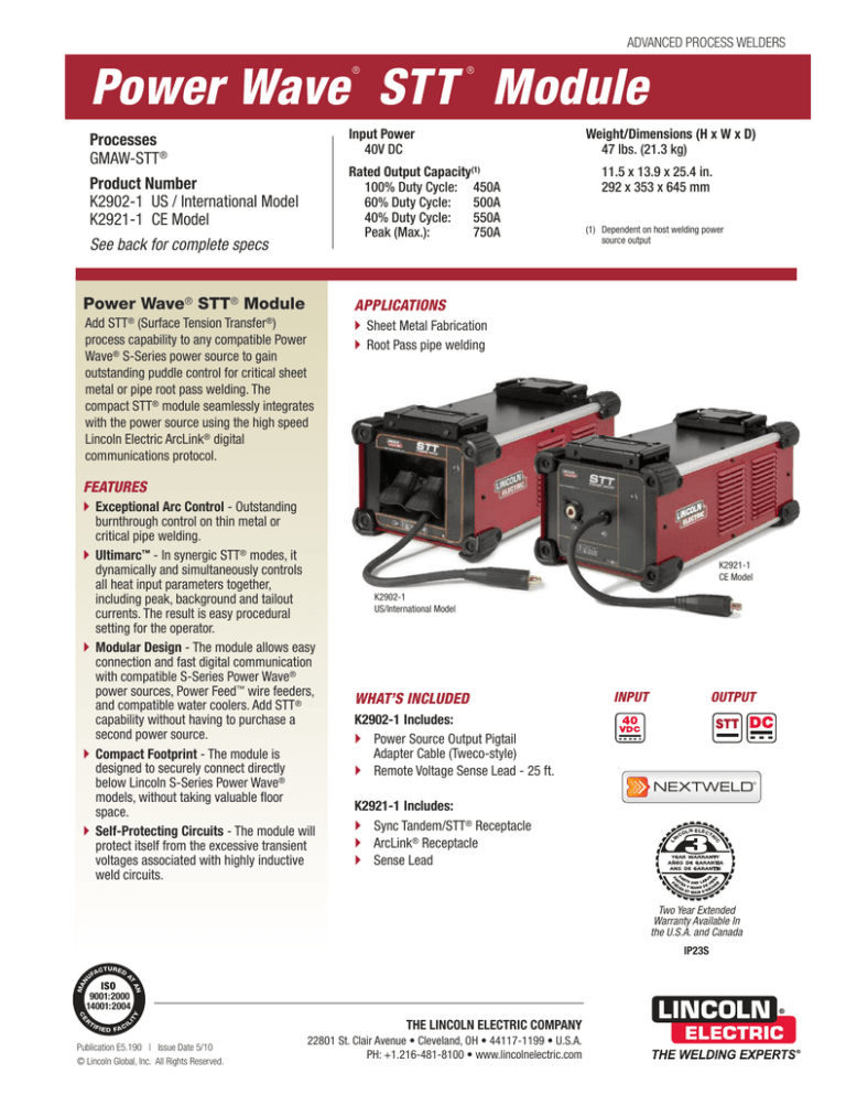
ADVANCED PROCESS WELDERS ® ® Power Wave STT Module Input Power 40V DC Processes GMAW-STT® Rated Output Capacity(1) 100% Duty Cycle: 450A 60% Duty Cycle: 500A 40% Duty Cycle: 550A Peak (Max.): 750A Product Number K2902-1 US / International Model K2921-1 CE Model See back for complete specs Power Wave® STT® Module Weight/Dimensions (H x W x D) 47 lbs. (21.3 kg) 11.5 x 13.9 x 25.4 in. 292 x 353 x 645 mm (1) Dependent on host welding power source output APPLICATIONS Add STT® (Surface Tension Transfer®) process capability to any compatible Power Wave® S-Series power source to gain outstanding puddle control for critical sheet metal or pipe root pass welding. The compact STT® module seamlessly integrates with the power source using the high speed Lincoln Electric ArcLink® digital communications protocol. Sheet Metal Fabrication Root Pass pipe welding FEATURES K2921-1 CE Model K2902-1 US/International Model WHAT’S INCLUDED OUTPUT INPUT K2902-1 Includes: Power Source Output Pigtail Adapter Cable (Tweco-style) Remote Voltage Sense Lead - 25 ft. ® K2921-1 Includes: Sync Tandem/STT® Receptacle ArcLink® Receptacle Sense Lead L NEXTWELD IN CO LN ELECT RI C Exceptional Arc Control - Outstanding burnthrough control on thin metal or critical pipe welding. Ultimarc™ - In synergic STT® modes, it dynamically and simultaneously controls all heat input parameters together, including peak, background and tailout currents. The result is easy procedural setting for the operator. Modular Design - The module allows easy connection and fast digital communication with compatible S-Series Power Wave® power sources, Power Feed™ wire feeders, and compatible water coolers. Add STT® capability without having to purchase a second power source. Compact Footprint - The module is designed to securely connect directly below Lincoln S-Series Power Wave® models, without taking valuable floor space. Self-Protecting Circuits - The module will protect itself from the excessive transient voltages associated with highly inductive weld circuits. Two Year Extended Warranty Available In the U.S.A. and Canada IP23S ISO 9001:2000 14001:2004 THE LINCOLN ELECTRIC COMPANY Publication E5.190 | Issue Date 5/10 © Lincoln Global, Inc. All Rights Reserved. 22801 St. Clair Avenue • Cleveland, OH • 44117-1199 • U.S.A. PH: +1.216-481-8100 • www.lincolnelectric.com WHAT IS STT ® (SURFACE TENSION TRANSFER®)? STT® (Surface Tension Transfer®) is a controlled GMAW short circuit transfer process that uses current controls to adjust the heat independent of wire feed speed, resulting in superior arc performance, good penetration, low heat input control, and reduced spatter and fumes. For more information see Nextweld® Document NX-2.20 STT® using CO2 and .045 in. solid wire. Note reduced spatter and fume. Conventional CV short circuit transfer using CO2 and .045 in. solid wire. A. STT® produces a uniform molten ball and maintains it until the “ball” shorts to the puddle. The STT® Process B. When the “ball” shorts to the puddle, the current is reduced to a low level allowing the molten ball to wet into the puddle. C. Automatically, a precision PINCH CURRENT wave form is applied to the short. During this time, special circuitry determines when the short is about to break and reduces the current to avoid the spatter producing “explosion”. D. STT® circuitry re-establishes the welding arc at a low current level. A B C D E A E. STT® circuitry senses that the arc is re-established, and automatically applies PEAK CURRENT, which sets the proper arc length. Following PEAK CURRENT, internal circuitry automatically switches to the BACKGROUND CURRENT, which serves as a fine heat control. Additionally, the TAILOUT ramp speed is controlled to provide a coarse heat control, returning the arc to the starting point (A). KEY CONTROLS CASE BACK DESCRIPTIONS CASE FRONT DESCRIPTIONS 1. Differential I/O Pigtail – Connects to the sync Tandem/STT® Receptacle on the rear of the power source. 1. Status LED – 2. STT INPUT – Connects to the Positive output of the power source. 2. ArcLink® Pigtail – Connects to the ArcLink® Out receptacle on the rear of the power source. 1. 1. 2. 3. 4. 3. STT OUTPUT – Connects to the wire feeder. 3. 3. Differential I/O (Sync Tandem) Output – Supports Synchronized Tandem MIG Welding with other compatible power sources. Note: This feature is not compatible with the STT process, and is therefore disabled when using STT weld modes. 2. K2902-1 US/International Model shown. NOTE: For operation with the K2823-1 Power Wave® S350 power source or K2862-1 Power Wave® S350 Ready-Pak® models with code numbers prior to 11600, the S28481 Retrofit Kit is required. Contact the Power Wave® Customer Service team in Cleveland, OH to order a kit at no charge to assure proper connection of the STT Module. 4. ArcLink® (Out) – Available on the K2902-1 US/International model only. Provides an ArcLink® pass through connection for all compatible ArcLink® wire feeders. [ 2 ] | Power Wave® STT ® Module APPLICATION DETAILS Using STT® for Open Root welding Open root welding is used for pipe and single-sided plate welding in situations that preclude welding from both sides of the material. This type of welding is common in the petrochemical and process piping industries. Open Root Pass with Stick Electrode Advantages of STT® Open Root • Penetration Control - Provides reliable root pass and complete back bead. Ensures excellent sidewall fusion. Stick welding with cellulose electrodes provides good fusion characteristics, but leaves deep wagon tracks (requiring more labor for grinding), a very convex root weld, and a high hydrogen deposit. • Cost Reduction - Uses 100% CO2, the lowest cost gas, when welding carbon steel. • Flexibility - Provides the capability of welding stainless steel, nickel alloys, and mild or high strength steels without compromising weld quality. - Capable of welding out of position. • Low Heat Input - Reduces burnthrough and distortion. • Low Hydrogen Weld Metal Deposit • Speed - High quality open root welds at faster travel speeds than GTAW. • Current Control Independent of Wire Feed Speed - Allows operator to control the heat input to the weld puddle. • Ease of Operator Use - More forgiving process than conventional short arc welding with CV machines. STT® Open Root Application Inside of an 8 in. x .375 in. wall API 5L-X52 pipe, welded in 5G position. Comparing STT® to conventional processes Advantages of STT® replacing short-arc GMAW: • Significantly reduces lack of fusion • Good puddle control • Capable of producing consistent X-ray quality welds • Reduced training time • Lower fume generation and spatter • Can use various compositions of shielding gas • 100% CO2 (on mild steel) Advantages of STT® replacing GTAW: • Four times faster than GTAW • Vertical down welding • Reduced training time • Can use various compositions of shielding gas • 100% CO2 (on mild steel) • Welds stainless, nickel alloys and mild steel • Consistent x-ray quality welds Power Wave® STT ® Module | [ 3 ] Open Root Pass with STT® provides a weld ligament thickness of approximately 0.22 in. Note these advantages: • Superior weld profile (no wagon tracks) • Slight convexity of root weld • Low hydrogen deposit WHEN to use STT® STT® is the process of choice for low heat input welds. STT® is also ideal for: • Open root – pipe and plate • Thin gauge material – automotive • Stainless steel and nickel alloy – petrochemicalutility and food industry • Silicon bronze automotive • Galvanized steel • Semiautomatic and robotic applications SETTING STT® PARAMETERS ® Non-Synergic STT Control Synergic STT Control Power Feed™ 10M Wire Feeder Non-Synergic Interface Control 1. Adjust WIRE FEED SPEED to: - Control the deposition rate 2. Adjust PEAK CURRENT to - Control the arc length Adjust BACKGROUND CURRENT to: - Control heat input (fine) Adjust TAILOUT to: - Control heat input (coarse) Adjust HOT START to: - Control the heat input at the start of the weld. 3. Adjust START / END OPTIONS to: - Modify PREFLOW time, RUN-IN WIRE FEED SPEED and START time as well as CRATER, BURNBACK and POSTFLOW time. Power Feed™ 10M Wire Feeder Synergic Interface Control 1. Adjust WIRE FEED SPEED to: - Control the deposition rate 2. Adjust TRIM to: - Change ball size or increase or decrease arc energy. 3. Adjust WELD MODE / ARC CONTROL to: - ULTIMARC™ dynamically modifies parameters to control heat input, including HOT START, PEAK, BACKGROUND and TAILOUT currents. 4. Adjust START / END OPTIONS to: - Modify PREFLOW time, RUN-IN WIRE FEED SPEED and START time as well as CRATER, BURNBACK and POSTFLOW time. ® 1. Voltage Not Applicable 1. 2. 2. 3. 3. 4. PRODUCT SPECIFICATIONS Product Name Product Number Input Power Rated Output Capacity(1) Current/Voltage/Duty Cycle HxWxD inches (mm) Net Weight lbs. (kg) Power Wave® STT® Module K2902-1 US/International 40 V DC 100% Duty Cycle: 450A 60% Duty Cycle: 500A 40% Duty Cycle: 550A Peak (Max.): 750A 11.5 x 13.9 x 25.4 (292 x 353 x 645) 47 (21.3) K2921-1 CE Model (1) Dependent on host welding power source output For best welding results with Lincoln Electric equipment, always use Lincoln Electric consumables. Visit www.lincolnelectric.com for more details. CUSTOMER ASSISTANCE POLICY The business of The Lincoln Electric Company is manufacturing and selling high quality welding equipment, consumables, and cutting equipment. Our challenge is to meet the needs of our customers and to exceed their expectations. On occasion, purchasers may ask Lincoln Electric for information or advice about their use of our products. Our employees respond to inquiries to the best of their ability based on information provided to them by the customers and the knowledge they may have concerning the application. Our employees, however, are not in a position to verify the information provided or to evaluate the engineering requirements for the particular weldment. Accordingly, Lincoln Electric does not warrant or guarantee or assume any liability with respect to such information or advice. Moreover, the provision of such information or advice does not create, expand, or alter any warranty on our products. Any express or implied warranty that might arise from the information or advice, including any implied warranty of merchantability or any warranty of fitness for any customers’ particular purpose is specifically disclaimed. Lincoln Electric is a responsive manufacturer, but the selection and use of specific products sold by Lincoln Electric is solely within the control of, and remains the sole responsibility of the customer. Many variables beyond the control of Lincoln Electric affect the results obtained in applying these types of fabrication methods and service requirements. Subject to Change – This information is accurate to the best of our knowledge at the time of printing. Please refer to www.lincolnelectric.com for any updated information.
