Generating Facility Standard Process Interconnection
advertisement
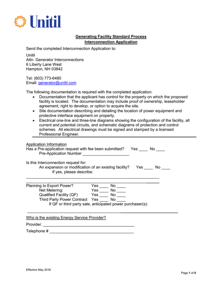
Generating Facility Standard Process Interconnection Application Send the completed Interconnection Application to: Unitil Attn. Generator Interconnections 6 Liberty Lane West Hampton, NH 03842 Tel: (603) 773-6480 Email: generator@unitil.com The following documentation is required with the completed application: Documentation that the applicant has control for the property on which the proposed facility is located. The documentation may include proof of ownership, leaseholder agreement, right to develop, or option to acquire the site. Site documentation describing and detailing the location of power equipment and protective interface equipment on property. Electrical one-line and three-line diagrams showing the configuration of the facility, all current and potential circuits, and schematic diagrams of protection and control schemes. All electrical drawings must be signed and stamped by a licensed Professional Engineer. Application Information Has a Pre-application request with fee been submitted? Yes ____ No ____ Pre-Application Number _____________________ Is this Interconnection request for: An expansion or modification of an existing facility? Yes ____ No ____ If yes, please describe: ____________________________________________________________ ____________________________________________________________ Planning to Export Power? Yes ____ No ____ Net Metering: Yes ____ No ____ Qualified Facility (QF) Yes ____ No ____ Third Party Power Contract Yes ____ No ____ If QF or third party sale, anticipated power purchaser(s): __________________________________________ Who is the existing Energy Service Provider? Provider: _________________________________________ Telephone # ______________________________________ Effective May 2016 Page 1 of 6 Contact Information Date Prepared___________ Legal Name and address of Interconnecting Customer Company Name: _________________________Contact Person: Mailing Address: City: State: Telephone (Daytime): (Evening): Facsimile Number: E-Mail Address: Zip Code: Alternative Contact Information (if different from Applicant) Name: Mailing Address: City: State: Telephone (Daytime): (Evening): Facsimile Number: E-Mail Address: Zip Code: Generating Facility Information Location (if different from above): Customer Name: _________________________Contact Person: Mailing Address: City: State: Zip Code: Telephone (Daytime): (Evening): Facsimile Number: E-Mail Address: Electric Service Company: Account Number (if available): Meter Number (if available): _________________ Total System Peak AC Rating (kW): __________________ (This is the sum of all Peak AC Nameplate Ratings.) Type of Generating Unit: Synchronous _______ Manufacturer: Induction_____ Inverter_____ Model: (If there are various multiple generators with various models, please specify in the Generating Facility Technical Detail section on following page(s) Effective May 2016 Page 2 of 6 Nameplate Rating (Peak AC): Real Power: ________(kW) Reactive Power: _______ (kVAr) at _______ (Volts) Single ______ or Three ______ Phase Prime Mover: Fuel Cell___ Recip Engine___ Gas Turb___ Steam Turb___ Microturbine___ PV___ Other Energy Source: Solar (Please Specify) Wind Other UL1741 Listed? Yes Est. Install Date: Hydro Diesel Natural Gas Fuel Oil (Specify) _________(Please Specify) No Est. In-Service Date: __________Agreement Needed By: _______ Application Process I hereby certify that, to the best of my knowledge, all of the information provided in this application is true: Customer Signature: Title: Date: Effective May 2016 Page 3 of 6 Generating Facility Technical Detail List components of the Generating Facility that are currently certified and/or listed to national standards Equipment Type Standard 1. Manufacturer Model National 2. 3. 4. 5. 6. Total Number of Generating Units in Facility? Generator Unit Power Factor Rating: Max Adjustable Leading Power Factor? Max Adjustable Lagging Power Factor? Generator Characteristic Data (for all inverter-based machines) Max Design Fault Contribution Current? Instantaneous or RMS Harmonics Characteristics: Start-up power requirements: Generator Characteristic Data (for all rotating machines) Rotating Frequency: Grounding Resistor (If Applicable): (rpm) Neutral Additional Information for Synchronous Generating Units Synchronous Reactance, Xd: (PU) Transient Reactance, X’d: (PU) Subtransient Reactance, X”d: (PU) Neg Sequence Reactance, X2: (PU) Zero Sequence Reactance, Xo: (PU) KVA Base: Field Voltage: (Volts) Field Current: (Amps) Additional information for Induction Generating Units Rotor Resistance, Rr: Stator Resistance, Rs: Rotor Reactance, Xr: Stator Reactance, Xs: Magnetizing Reactance, Xm: Short Circuit Reactance, Xd”: Exciting Current: Temperature Rise: Effective May 2016 Page 4 of 6 Frame Size: Total Rotating Inertia, H: Per Unit on KVA Base: Reactive Power Required In Vars (No Load): Reactive Power Required In Vars (Full Load): Additional information for Induction Generating Units that are started by motoring Motoring Power: (kW) Design Letter: Interconnection Facilities Technical Detail Will a transformer be used between the generator and the point of interconnection? No Yes Will the transformer be provided by Customer? No Yes Transformer Data (if applicable, for Customer-Owned Transformer): Nameplate Rating: (kVA) Transformer Impedance: If Three Phase: Transformer Primary: Single (%) on a or Three Phase KVA Base (Volts) ___Delta ____ Wye _____ Wye Grounded ____ Other Transformer Secondary: _____ Wye Grounded ____ Other (Volts) ___Delta ____ Wye Transformer Fuse Data (if applicable, for Customer-Owned Fuse): (Attach copy of fuse manufacturer’s Minimum Melt & Total Clearing Time-Current Curves) Manufacturer: Type: Size: Speed: Interconnecting Circuit Breaker (if applicable): Manufacturer: Type: Load Rating: Interrupting Rating: Trip Speed: (Amps) (Amps) (Cycles) Interconnection Protective Relays (if applicable): (If microprocessor-controlled) List of Functions and Adjustable Setpoints for the protective equipment or software: Setpoint Function Minimum Maximum 1. 2. 3. 4. 5. 6. Effective May 2016 Page 5 of 6 (If discrete components) (Enclose copy of any proposed Time-Overcurrent Coordination Curves) Manufacturer: Type: Style/Catalog No.: Proposed Setting: Manufacturer: Type: Style/Catalog No.: Proposed Setting: Manufacturer: Type: Style/Catalog No.: Proposed Setting: Manufacturer: Type: Style/Catalog No.: Proposed Setting: Manufacturer: Type: Style/Catalog No.: Proposed Setting: Current Transformer Data (if applicable): (Enclose copy of Manufacturer’s Excitation & Ratio Correction Curves) Manufacturer: Type: Accuracy Class: Proposed Ratio Connection: Manufacturer: Type: Accuracy Class: Proposed Ratio Connection: Potential Transformer Data (if applicable): Manufacturer: Type: Accuracy Class: Proposed Ratio Connection: Manufacturer: Type: Accuracy Class: Proposed Ratio Connection: Effective May 2016 Page 6 of 6
