ASXP Series AC Current Sensor
advertisement
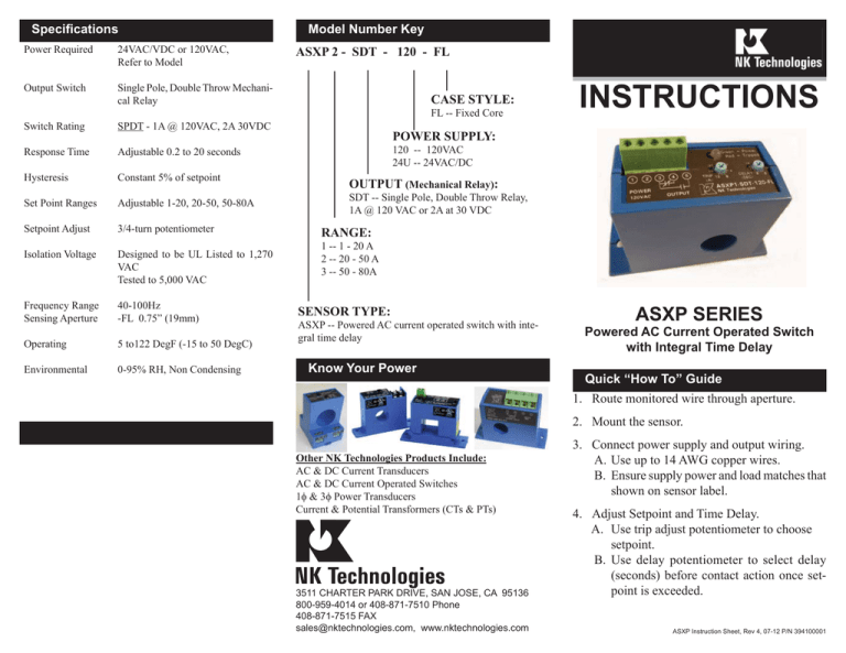
Specifications Power Required 24VAC/VDC or 120VAC, Refer to Model Output Switch Single Pole, Double Throw Mechanical Relay Model Number Key ASXP 2 - SDT - 120 - FL CASE STYLE: FL -- Fixed Core Switch Rating SPDT - 1A @ 120VAC, 2A 30VDC Response Time Adjustable 0.2 to 20 seconds Hysteresis Constant 5% of setpoint Set Point Ranges Adjustable 1-20, 20-50, 50-80A Setpoint Adjust 3/4-turn potentiometer Isolation Voltage Designed to be UL Listed to 1,270 VAC Tested to 5,000 VAC Frequency Range Sensing Aperture 40-100Hz -FL 0.75” (19mm) Operating 5 to122 DegF (-15 to 50 DegC) Environmental 0-95% RH, Non Condensing INSTRUCTIONS POWER SUPPLY: 120 -- 120VAC 24U -- 24VAC/DC OUTPUT (Mechanical Relay): SDT -- Single Pole, Double Throw Relay, 1A @ 120 VAC or 2A at 30 VDC RANGE: 1 -- 1 - 20 A 2 -- 20 - 50 A 3 -- 50 - 80A SENSOR TYPE: ASXP -- Powered AC current operated switch with integral time delay Know Your Power ASXP SERIES Powered AC Current Operated Switch with Integral Time Delay Quick “How To” Guide 1. Route monitored wire through aperture. 2. Mount the sensor. Other NK Technologies Products Include: AC & DC Current Transducers AC & DC Current Operated Switches 1φ & 3φ Power Transducers Current & Potential Transformers (CTs & PTs) 3511 CHARTER PARK DRIVE, SAN JOSE, CA 95136 800-959-4014 or 408-871-7510 Phone 408-871-7515 FAX sales@nktechnologies.com, www.nktechnologies.com 3. Connect power supply and output wiring. A. Use up to 14 AWG copper wires. B. Ensure supply power and load matches that shown on sensor label. 4. Adjust Setpoint and Time Delay. A. Use trip adjust potentiometer to choose setpoint. B. Use delay potentiometer to select delay (seconds) before contact action once setpoint is exceeded. ASXP Instruction Sheet, Rev 4, 07-12 P/N 394100001 Description ASXP Series products are powered, current-operated switches which trigger when sensed current levels exceed the adjusted setpoint. Models are available with NO and NC mechanical relay contacts. Contact action can be delayed for up to 20 seconds by using the Time Delay Adjust potentiometer. Power Supply and Output Wiring Power Supply Output Contacts Bi-color LED indicates power (green) and tripped contacts (red) Time delay adjustment pot w/ arrow indication. Turn CW to increase contact time delay. Installation Trip point adjustment pot w/ arrow indication. Turn CW to increase setpoint. ASXP switches can be located in the same environment as motors, contactors, heaters, pull-boxes, and other electrical enclosures. Mounting can be done in any position or hung directly on wires with a wire tie. Ensure at least one inch clearance exists between sensor and other magnetic devices. Run wire to be monitored through aperture (opening) in the sensor. For control or monitoring wiring, use up to 14 AWG copper wire and tighten terminals to 5 inch-pounds torque. Be sure the output load does not exceed the switch rating. Connect power supply to terminals 1 and 2 on the sensor. Check to ensure supply power matches voltage and type required by sensor. Once powered, the LED on the unit should indicate unit is on by glowing green. Connect output wiring to terminals 3 and 5 for the normally open (closes on current rise) or 3 and 4 for the normally closed (opens on current rise) contact. Note that if unit is powered and monitored conductor has current flow, the output contacts may energize depending on setpoint and time delay settings. The sensor will delay the initial contact action for two seconds, then after the initial sensing of current the delay can be set from no delay (operates in 200ms) up to 20 seconds. The initial delay is designed to keep the sensor from tripping on motor inrush current. Setpoint Adjustment ASXP Series setpoint and time delay are adjusted through two 3/4-turn pots which have arrow indication of the selected value. The unit comes from the factory with setpoint set to its maximum (fully clockwise CW) and time delay set to the lowest level (fully counter-clockwise CCW). Typical Adjustment 1. Turn the Trip pot to minimum setpoint. (Fully CCW, 1A, 20A , or 50A depending on model). Ensure Delay pot is at 0 sec. (Fully CCW). 2. Ensure normal operating current running through sensor. The output should be tripped since the pot is at its minimum setpoint and bi-color LED should change from green to red, indicating contacts are energized. 3. Turn the Trip pot CW until the unit un-trips. This is indicated by the LED changing color from red to green and by the changing of the output switch status. 4. Now turn the Trip pot CCW slowly until the unit trips again. It is now set at the current level being monitored. This value can be confirmed by reading the trip point off the graded scale of the trip pot. A. To Set UNDERLOAD - Turn pot slightly CCW. B. To Set OVERLOAD - Turn pot slightly CW. 5. Adjust the Delay of the contact action in the same fashion. Increase time delay by turning pot CW to desired value using scale on Delay potentiometer. Trouble Shooting 1. Sensor is always tripped A. The setpoint may be too low. Turn pot CW to increase setpoint. B. Switch has been overloaded and contacts are burned out. Check the output load, remembering to include inrush on inductive loads (coils, motors, ballasts) 2. Sensor will not trip A. The setpoint may be too high. Turn pot CCW to decrease setpoint. B. Monitored current is below minimum required. Loop the monitored wire several times through the aperture until the “sensed” current rises above minimum. Sensed Amps = (Actual Amps) x (Number of Loops). Count loops on the inside of the aperture. C. Switch has been overloaded and contacts are burned out. Check the output load, remembering to include inrush on inductive loads (coils, motors, ballasts).
