3-PHASE INDUCTION MOTORS EXAMPLES OF MOTOR
advertisement

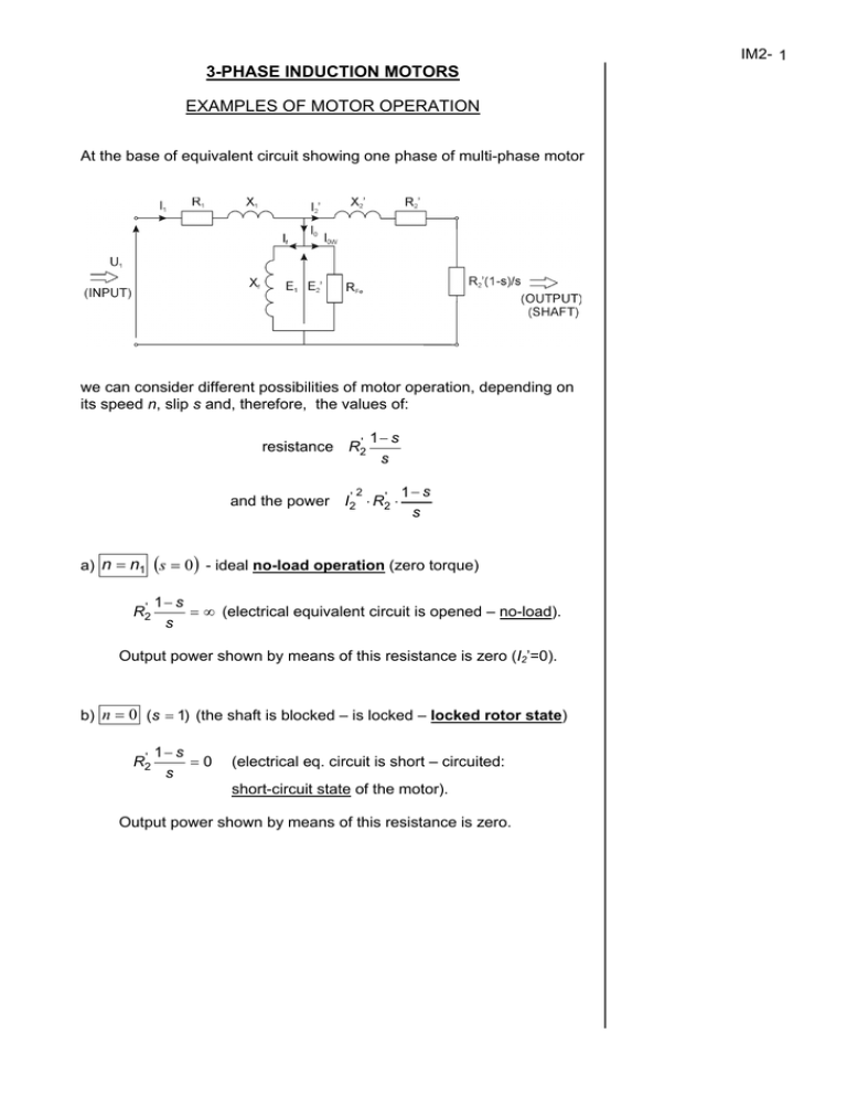
3-PHASE INDUCTION MOTORS EXAMPLES OF MOTOR OPERATION At the base of equivalent circuit showing one phase of multi-phase motor we can consider different possibilities of motor operation, depending on its speed n, slip s and, therefore, the values of: resistance R2' 2 1− s s and the power I2' ⋅ R2' ⋅ 1− s s a) n = n1 (s = 0 ) - ideal no-load operation (zero torque) R2' 1− s = ∞ (electrical equivalent circuit is opened – no-load). s Output power shown by means of this resistance is zero (I2’=0). b) n = 0 (s = 1) (the shaft is blocked – is locked – locked rotor state) R2' 1− s =0 s (electrical eq. circuit is short – circuited: short-circuit state of the motor). Output power shown by means of this resistance is zero. IM2- 1 IM2- 2 c) Operation of induction machine with 0 < n < n1 (motor operation) Sankey’s diagram – energy (power) balance diagram: P1 = m1 I 1U 1 cos ϕ ∆PCu1 = m1I12R1 - stator copper loss ( m1 - number of phases) ∆PFe - stator core loss (can be determined from the no-load test) The remainder: Pe = P1 − ∆PCu1 − ∆PFe is called “electromechanical power” or “ideal power”. Physically it is power transferred from the stator to rotor by means of magnetic field (through the air gap). It is a power delivered to the rotor! From the equivalent circuit: R' Pe = m1I2'2 2 = m1I2'2R2' s + rotor copper loss ∆PCu 2 ∆PCu 2 = sPe 1− s m1I2'2R2' s “mechanical power” Pm or “rotor developed power” Pm = Pe − ∆PCu 2 From the first relation:→ the value of slip s should be as small as possible to limit the value of rotor copper loss. In practice s is at the range of several %, therefore f 2 = sf 1 is very small and rotor iron (core) loss is small and can be neglected. After subtraction mechanical loss (power loss due to friction & windage of rotating rotor) from Pm we get: Pm − ∆Pm = P2 (or Pout or P ) – shaft output power Efficiency of energy (power) conversion: η= P2 Pout = P1 Pin For further consideration let’s take the mechanical power which corresponds to the power appearing across the resistance R2' 1− s . This s power is connected with the torque- electromechanical torque – rad driving the rotor with the speed n (or Ω in ): s 1− s Pm = m1I2'2R2' s Electromechanical torque Te = Pm Ω = 60m1 1− s I2'2R2' 2πn1(1 − s ) s in [N⋅m] or [Nm] Rotor core loss is not even shown at Sankey’s diagram. IM2- 3 From simplified equivalent circuit: With two following simplifications: ‘ R2' - and can s a) R1 << be neglected, b) parallel branch is neglected, I2' = U1 (X 1+ ) 2 X 2' R' + 2 s 2 Substitution I 2' to Te relation yields: Te = 60m1 ⋅ 2πn1 ( R2' U12 s X1 + ) 2 X 2' In general Te = f (s, U1, f , R2 ) R '2 + 2 s The torque developed in the machine is proportional to the voltage squared. Testing of the function Te = f (s ) for U, f , R2 = const yields the following results: torque–slip curve There are two critical points 60m1 U12 Tmax = ± ⋅ 2πn1 2 X1 + X 2' breakdown torque – maximum torque that can be developed in IM for given voltage U 1 and frequency f . ( ) Tmax doesn’t depend upon R2 ! smax = ± R2' X1 + X 2' breakdown slip smax ∼ R2 ! The same result in other coordinates Kloss formula torque–speed curve T Tmax = 2 smax s + s smax Ts - starting torque. Usually smax is at the range of about 10%. Notice that the maximum (breakdown) torque is proportional to the voltage squared and inversely proportional to frequency squared (n1 and X ∼ f). IM2- 4 STABILITY OF THE MOTOR OPERATION The motor operates with constant speed when torque balance is zero: Te − Tload = 0 From two possible points A & B only point B corresponds to stable operation. Stable region of T-n curve Stable region is for 0 < s < smax N - point of nominal operation ( TN ; n N - nominal torque, nominal speed). Adequate surplus of stability is required. Usually minimum value of torque ratio required by users is 2: Tmax ≥2 TN stability margin For motor driving the load having fan-type torque-speed characteristic it can happen that stable operation occurs for very low speed: Such operation is very dangerous for normal construction motor: n≈ 1 s ≈ 0,5 n1 2 ∆PCu 2 ≈ 0,5Pe what means: - very high rotor copper loss!, - very low efficiency!. IM2- 5 NUMERICAL EXAMPLE Consider a 3-phase induction machine (motor) of rating: PN = 75 kW UN = 220/380 V cosϕN = 0.85 ηN = 0.92 f = 50 Hz nN = 975 rev/min ∆Pm = 0.5%PN R1 = 0.033 Ω rated power (always must be understood as output one) rated voltage (for two possible connections) rated power factor rated efficiency rated speed mechanical loss at rated speed stator winding (phase) resistance Calculate: 1) Nominal stator current (line) for star and delta connections of stator winding, 2) Apparent nominal power SN (power drawn by the stator from the line), 3) Active and reactive power absorbed from the mains for nominal load, 4) Nominal torque and nominal slip, 5) Iron core loss. 1. I1NY = I1N∆ = P1N 3UN cosϕ N PN 3UNηN cosϕ N 2. S1N = 3. P1N = PN = 3UNηNcosϕ N = = 75 × 103 3 × 380 × 0.92 × 0.85 75 × 103 3 × 220 × 0.92 × 0.85 = 145.7 A = 251.7 A P1N 75 = = 95.9 kVA cosϕ N 0.92 × 0.85 PN ηN = 75 = 81.52 kW 0.92 Q1N = S1N sinϕ N = 95.9 1 − 0.852 = 50.5 kvar 75 × 103 PN = 9.55 × = 734.6 N ⋅ m 975 nN n − nN 1000 − 975 sN = 1 = = 0.025 sN = 2.5% n1 1000 4. TN = 9.55 5. 2 ∆PCu1N = 3INph R1 = 3 × 145.72 × 0.033 = 2.102 kW Pe = P1N − ∆PFeN − ∆PCu1N PN = Pm − ∆Pm = Pe (1 − s ) − ∆Pm from this set of equations the unknown ∆PFeN is ∆PFeN = P1N − ∆PCu1N − PN + ∆Pm 75(1 + 0.005 ) = 81.52 − 2.102 − = 2.11 kW 1− s 1 − 0.025 BASIC CONSTRUCTIONS OF INDUCTION MACHINE Slip-ring induction machine Idea of construction Example of connections Basic characteristics IM2- 6 Squirrel-cage machine (squirrel-cage motor, cage motor) Different possible profiles of rotor slots and cage bars Double-cage motor Deep-bar rotor (deep-bar squirrel-cage induction motor) IM2- 7 IM2- 8 STARTING OF INDUCTION MOTORS Slip-ring motor starting Cage motor starting Star-delta starting (most popular for the motors of rated power above 5 kW). NUMERICAL EXAMPLE About induction motor of rating as in previous numerical example: PN = 75 kW UN = 220/380 V cosϕN = 0.85 ηN = 0.92 f = 50 Hz nN = 975 rev/min ∆Pm = 0.5%PN R1 = 0.033 Ω we know that it is a squirrel cage motor having the breakdown torque ratio Tmax/TN=Tb/TN=2.2, starting torque ratio Ts/TN=1.3 and rated starting current ratio IsN/IN=6. Calculate: 1. Values of starting torque and currents for direct switch-on starting (at nominal conditions of supply), 2. Starting torque and current for Y/∆ starting. 1. a) for Y connection (stator connected in Y, U=UN=380 V) TsN=1.3×TN=1.3×734.6=954.98 N⋅m IsNY=6×INY=6×145.7=874.2 A b) for ∆ connection (stator connected in ∆, U=UN=220 V) TsN=1.3×TN=1.3×734.6=954.98 N⋅m IsN∆=6×IN∆=6×251.7=1510.2 A 2. stator circuit connected in Y and supplied from the mains 3×220 V: 1 IsY = 3 × 6 × INY = 6 3 × 145.7 = 504.72 A 1 × 6 × INY IsY 1 3 = = IsN∆ 3 6 × 3 × INY TsY U = UN 2 2 1 1 1 TsN = TsN = TsN = × 954.98 = 318.33 N ⋅ m 3 3 3 IM2- 9 SPEED CONTROL OF INDUCTION MOTOR By means of rotor resistance By means of line voltage By means of slip-power recovery IM2- 10 By means of frequency SPECIAL APPLICATION OF INDUCTION MACHINE INDUCTION REGULATOR Rotor position is controlled by means of worm gear (worm/pinion device). Controlled voltage (AC) source 0 ÷ 2V1 (laboratory application). IM2- 11


