DIFFERENTIAL AMPLIFIER, SINGLE
advertisement

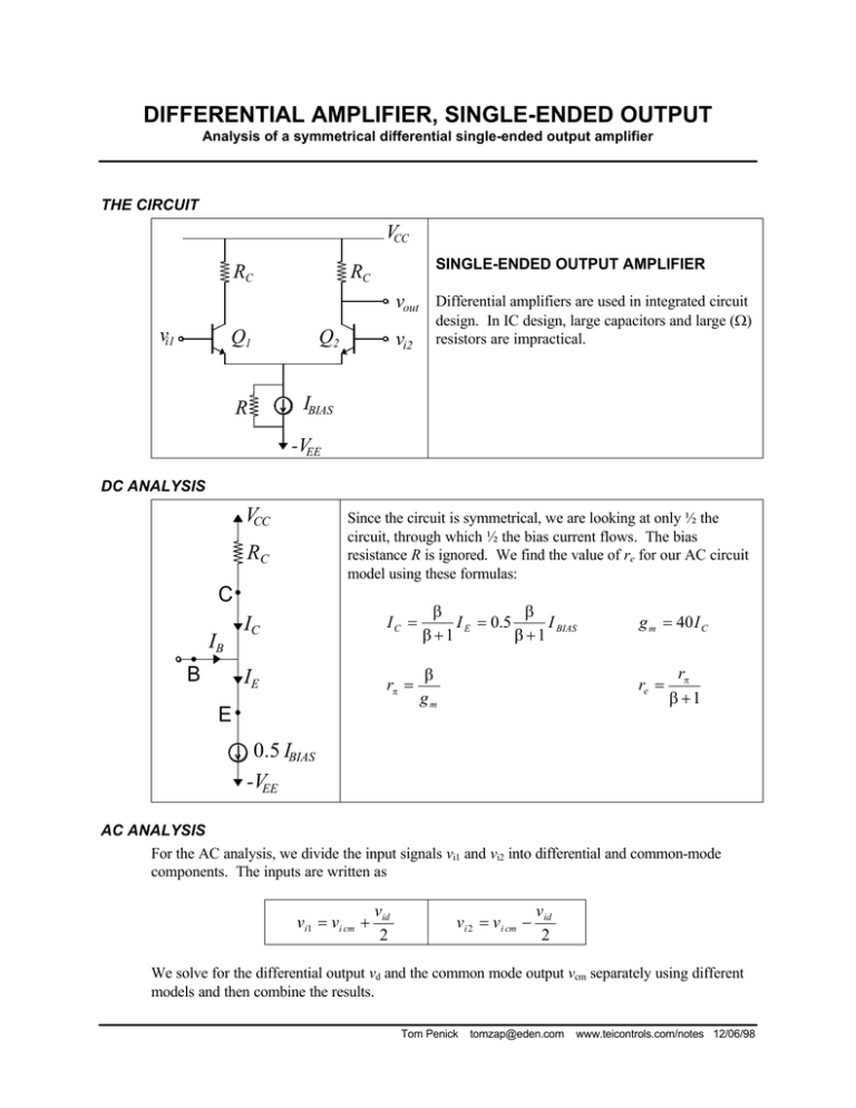
DIFFERENTIAL AMPLIFIER, SINGLE-ENDED OUTPUT Analysis of a symmetrical differential single-ended output amplifier THE CIRCUIT VCC RC SINGLE-ENDED OUTPUT AMPLIFIER RC vout vi1 Q1 Q2 R IBIAS vi2 Differential amplifiers are used in integrated circuit design. In IC design, large capacitors and large (Ω) resistors are impractical. -VEE DC ANALYSIS VCC Since the circuit is symmetrical, we are looking at only ½ the circuit, through which ½ the bias current flows. The bias resistance R is ignored. We find the value of re for our AC circuit model using these formulas: RC C IB B IC IC = β β I E = 0.5 I BIAS β +1 β +1 g m = 40 I C IE rπ = β gm re = E rπ β +1 0.5 IBIAS -VEE AC ANALYSIS For the AC analysis, we divide the input signals vi1 and vi2 into differential and common-mode components. The inputs are written as vi1 = vi cm + vid 2 vi 2 = v i cm − v id 2 We solve for the differential output vd and the common mode output vcm separately using different models and then combine the results. Tom Penick tomzap@eden.com www.teicontrols.com/notes 12/06/98 DIFFERENTIAL MODE ANALYSIS - solving for the differential mode voltage gain Ad DM MODEL Since the circuit is symmetrical and the differential mode inputs are 180° out of phase, a ground potential results at the emitters. The two halves of the circuit are isolated. Since there is an output only on the right-hand half, this is the only part of the circuit we include in this analysis. RC ic β ib vout ie = − vid 2 vi d 2 ÷ re = − v d out = −ic RC = ie re vi d ic = 2re β vi d β + 1 2re RC β vi d − β + 1 2re Ad = v d out vi d Ad is the differential mode gain [V/V] COMMON MODE ANALYSIS - solving for the common mode voltage gain Acm AC ANALYSIS RC RC Q1 2R ie = vi cm re + 2 R Q2 CM MODEL RC ic βib vi cm Even though we have looked only at the right-hand side in both phases of the analysis, the presence of the left-hand side does significantly affect the outcome. 2R ic = Because of the symmetry of the circuit, we can write R as two parallel 2R resistors and observe that no current flows between them. Therefore this connection can be eliminated and we separate the circuit into halves. Once again, we need only look at the right-hand half since that contains the output. β vi cm β + 1 re + 2 R vcm out = −ic RC = β vid β + 1 2re vout ie re 2R RC Acm = vcm out vi cm COMMON MODE REJECTION RATIO (CMRR) CMRR = Ad Acm CMRR dB = 20 log 10 Tom Penick tomzap@eden.com Ad Acm www.teicontrols.com/notes 12/06/98


