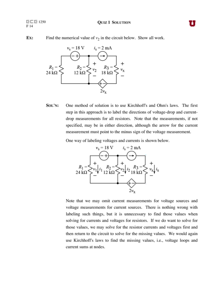
EX: Find the numerical value of v2 in the circuit below. Show all work
advertisement

QUIZ 1 SOLUTION 1250 F 14 EX: Find the numerical value of v2 in the circuit below. Show all work. SOL'N: One method of solution is to use Kirchhoff's and Ohm's laws. The first step in this approach is to label the directions of voltage-drop and currentdrop measurements for all resistors. Note that the measurements, if not specified, may be in either direction, although the arrow for the current measurement must point to the minus sign of the voltage measurement. One way of labeling voltages and currents is shown below. Note that we may omit current measurements for voltage sources and voltage measurements for current sources. There is nothing wrong with labeling such things, but it is unnecessary to find those values when solving for currents and voltages for resistors. If we do want to solve for those values, we may solve for the resistor currents and voltages first and then return to the circuit to solve for the missing values. We would again use Kirchhoff's laws to find the missing values, i.e., voltage loops and current sums at nodes. Next, we color the nodes in the circuit and look for components in series. The components in series carry the same current, allowing us to reduce the current variables in a branch to a single one. We see that vs is in series with R1, and is is in series with R3 and the 2vx source. It follows that i1 flows in vs, and is = 2 mA flows in R3 and the 2vx source. In the latter case, we have components in series with a current source, and the branch is ruled by the current source. The components in series with the current source have no impact on the rest of the circuit, which sees only the 2 mA of the current source; R3 and the 2vx source are invisible to the rest of the circuit. Thus, we may ignore R3 and the 2vx source going forward. They have been solved: vx = is R3 = 2 mA ⋅18 kΩ = 36V (1) This logic applies in general to components in series with current sources. These components only change the voltage drop across the current source. We are ready to start voltage loops. There is only one loop that avoids current sources, shown in red below. We could follow the loop in either direction. Here we go clockwise, and we will use the voltage sign where we enter a component. We get the following voltage-loop equation: −v1 − vs + v2 = 0V (2) For current sums, we have two extraordinary nodes: We only need one of the extraordinary nodes, as the second one involves the same currents as the other. Using the top node and summing the currents out of the node, we get the following equation: i1 + i2 + 2 mA = 0 A (3) Now we add Ohm's law equations for the resistors. v1 = i1R1 or i1 = v1 / R1 (4) v2 = i2 R2 or i2 = v2 / R2 (5) We now have four equations in four unknowns, i1, i2, v1, and v2. From this point forward, we have an algebra problem that we could solve in a variety of ways. What follows in one possible approach. Since we are seeking a voltage as our answer, we will use the Ohm's law equations to eliminate the current variables. Equation (2) is already in terms of voltages, so we only need to modify (3). v1 v + 2 + 2 mA = 0 A 24 kΩ 12 kΩ Now we have two equations in two unknowns, (2) and (6). (6) Now we eliminate v1 by writing v1 in terms of v2. v1 = v2 − vs (7) Substituting (7) into (6), we have an equation with only one unknown, v2: v2 − vs v + 2 + 2 mA = 0 A 24 kΩ 12 kΩ We factor out v2 and we place constant terms on the right side. ⎛ 1 1 ⎞ vs + ⎜⎝ 24kΩ 12 kΩ ⎟⎠ v2 = 24 kΩ − 2 mA We divide both sides by the multiplier of v2, and then we multiply the numerator and denominator by the common denominator, to clear the fractions. vs vs − 2 mA − 2 mA 24 kΩ 24 kΩ 24 kΩ v2 = = ⋅ 1 1 1 1 24 kΩ + + 24kΩ 12 kΩ 24kΩ 12 kΩ or v − 48V 18V − 48V −30V v2 = s = = = −10V 1+ 2 1+ 2 3 Another method of solving this problem is to do a source transformation on the left side, but first we simplify the right branch to is, as described above. Then we transform the left side from a Thevenin form to a Norton form. Now we argue that v2 appears across R1 and R2, and v2 will appears across the equivalent of R1 parallel R2. The current sources may be summed, since they are in parallel. Since our measurement direction is up (our choice) we use positive is2 (in the same direction, up) and negative is (opposite direction, down). By Ohm's law, we have our answer: v2 = (is2 − is )R1 || R2 = −1.25 A ⋅ 8 kΩ = −10V Note that the current measurement on the left measures current flowing up, over, and then down on the right side. For the resistor, this corresponds to a downward current measurement error, which obeys the passive sign convention. Thus, we don't need a minus sign in our voltage calculation.


