Seebeck and Peltier Effects - Department of Physics and Astronomy
advertisement

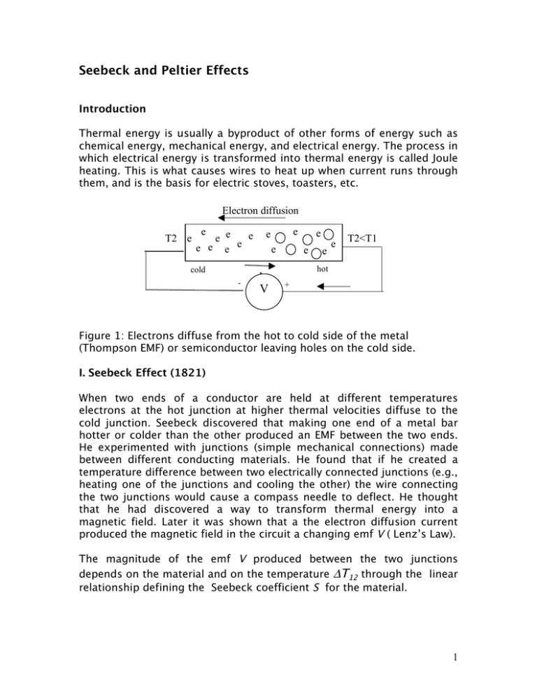
Seebeck and Peltier Effects Introduction Thermal energy is usually a byproduct of other forms of energy such as chemical energy, mechanical energy, and electrical energy. The process in which electrical energy is transformed into thermal energy is called Joule heating. This is what causes wires to heat up when current runs through them, and is the basis for electric stoves, toasters, etc. Electron diffusion T2 e e e e e e e e e cold - e e e I V e e e e T2<T1 hot + Figure 1: Electrons diffuse from the hot to cold side of the metal (Thompson EMF) or semiconductor leaving holes on the cold side. I. Seebeck Effect (1821) When two ends of a conductor are held at different temperatures electrons at the hot junction at higher thermal velocities diffuse to the cold junction. Seebeck discovered that making one end of a metal bar hotter or colder than the other produced an EMF between the two ends. He experimented with junctions (simple mechanical connections) made between different conducting materials. He found that if he created a temperature difference between two electrically connected junctions (e.g., heating one of the junctions and cooling the other) the wire connecting the two junctions would cause a compass needle to deflect. He thought that he had discovered a way to transform thermal energy into a magnetic field. Later it was shown that a the electron diffusion current produced the magnetic field in the circuit a changing emf V ( Lenz’s Law). The magnitude of the emf V produced between the two junctions depends on the material and on the temperature ΔT12 through the linear relationship defining the Seebeck coefficient S for the material. 1 ΔV = S ΔT12 The Seebeck coefficient can be measured Figure 2, by connecting wire-A in a circuit with 2 wire-Bs. The two junctions (ends of wire-A ) are held at two temperatures, and V measured as T1 or T2 is varied, Diagram of. Figure 2: Experimental setup for measuring the Seebeck coefficient S. Only terminals 1 and 2 need be considered if the B-leads at the voltmeter are kept at the same temperature. If T1>T2 electrons flow to T1 leaving T2 more positive. Vb-Va = SA(T2-T) Vc-Vb= SB(T1-T2) Vd-Vc= SA(T-T1) V = (Vb-Va)+ (Vc-Vb) + (Vd-Vc) V = SA T2 – SA T +SB T1 –SB T2 + SA T – SA T1 V = SA(T2-T1) - SB(T2-T1) = (SA-SB)(T2-T1) Q = q V = q (SA-SB)(T2-T1) dQ/dt = I (SA-SB)(T2-T1) = I Π 12 Procedure 1. Measure the ΔV across different materials (Cu, PbSn, Al (as shown in Figure 1, above) with T1~0oC and T2=100oC. Determine the Seebeck Coefficients from S = ΔV /ΔT12 2. Compare the measured coefficients with standard results. 3. Plot ΔV vs ΔT for CU and Al. 2 T(degC) 50 55 60 65 70 75 80 85 90 95 100 Cu(uV) 54 57 60 64 67 72 76 78 82 88 93 Cu(uV) 42 46 50 54 59 62 66 68 72 76 83 Al(uV) -52 -68 -70 -72 -77 -80 -87 -111 -122 y = -4.2x + 288 3 II. Thermocouple A thermocouple, a temperature measuring device can be made by holding all but one terminal (say T1) to the same temperature. Procedure 1. Create two junctions between two different materials (as shown in Figure 1, above) by twisting wires firmly together. As shown in the diagram, you'll need one length of the first material, and two lengths of the second material. 2. Set your voltmeter to the most sensitive DC voltage (usually 50 or 200 mV). 3. Attach the voltmeter leads to the two free ends (as shown in Figure 1, above.) The test leads with alligator clips will be useful for this. 4. Measure and record the voltage with both junctions at room temperature. 5. Insert one junction in a cold liquid or place it against an ice block and measure and record the voltage again (leave the other junction at room temperature). 6. Insert the other junction in hot liquid or put it in the flame of a candle. Measure and record the voltage again. Be careful with this step! Avoid touching the heated wires! 7. Repeat the experiment using different pairs of materials to create the junctions. 8. Make a graph of the voltage vs. temperature difference for each kind of junction. 9. Which pair of materials gives you the best results (i.e., highest voltage measured for the same temperature difference)? 4 III. Peltier Effect (1834) The reverse of the Seebeck effect is also possible: by passing a current through two junctions, you can create a temperature difference. This process was discovered in 1834 by scientist named Peltier, and thus it is called the Peltier effect. This may sound similar to Joule heating described above, but in fact it is not. In Joule heating the current is only increasing the temperature in the material in which it flows. In Peltier effect devices, a temperature difference is created: one junction becomes cooler and one junction becomes hotter. Although Peltier coolers are not as efficient as some other types of cooling devices, they are accurate, easy to control, and easy to adjust. Peltier effect devices are used coolers for microelectronic devices such as microcontrollers and computer CPUs. This use is very common among computer hobbyists to help them in over-clocking the microprocessors for more speed without causing the CPU to overheat and break in the process. T T2> T1 T - - p -B + ++ -- - n-A ++ + -- - p-B ++ + a b c d + V - Figure 5: Two dissimilar metals or semiconductors connected at b and c. The junction at T1 heats up while the junction at T3 cools. Vb-Va = SA(T2-T) Vc-Vb= SB(T1-T2) Vd-Vc= SA(T-T1) V = (Vb-Va)+ (Vc-Vb) + (Vd-Vc) V = SA T2 – SA T +SB T1 –SB T2 + SA T – SA T1 V = SA(T2-T1) - SB(T2-T1) = (SA-SB)(T2-T1) Q = q V = q (SA-SB)(T2-T1) dQ/dt = I (SA-SB)(T2-T1) = I Π 12 5 Procedure 1. Use the Junctions created in the junctions in the Seebeck effect experiment, above. 1kΩ 2. In series with a 10V power supply place a current limiting 1kΩ resistor. 3. To observe the temperature of the junctions, you can put a drop of water on each one. (Do not touch the junctions! One can get hot enough to cause a burn!) Does the water freeze on one of the junctions? What happens if you then reverse the polarity of the battery connection? 4. Repeat the experiment with different junction materials. 6 Variations * The Seebeck effect experiment can be expanded to create a real temperature sensor. You will need an independent means of measuring the temperature difference between the two junctions to calibrate your device. * For a more advanced Peltier effect experiment, you can vary the current and measure the temperature difference created. You'll need to figure out a method for measuring the temperature of each junction. Use different resistors to change the current. Use Ohm's Law (http://www.physics.uoguelph.ca/tutorials/ohm/Q.ohm.intro.html) to calculate how much current will flow in the circuit. Also calculate how much power will be dissipated in the resistor (and be sure to use a resistor with sufficient wattage rating). Plot the temperature difference vs. current for each type of junction. * Advanced. You can get a commercial Peltier effect device and study its temperature vs. current characteristics. Credits http://www.sciencebuddies.org/mentoring/project_ideas/Elec_p031.sht ml By Akram Salman AMD logo Bibliography * To learn about Seebeck effect check the following websites: o Wikipedia contributors, 2006. "Thermoelectric Effect," Wikipedia, The Free Encyclopedia [accessed May 22, 2006] http://en.wikipedia.org/w/index.php?title=Thermoelectric_effect&oldid=53657667. o Kuphaldt, T.R., 2003. "Thermoelectricity," All About Circuits: Volume VI— Experiments [accessed May 22, 2006] http://www.allaboutcircuits.com/vol_6/chpt_3/10.html. o Thermoelectrics.com, 2005. "Introduction to Thermoelectrics," Thermoelectrics.com [accessed May 22, 2006] http://www.thermoelectrics.com/introduction.htm. * For learning about the Peltier effect check the following website: Steinbrecher, T., 2005. "The Heatsink Guide: Peltier Cooler Information," HeatsinkGuide.com [accessed May 22, 2006] http://www.heatsink-guide.com/peltier.htm. * To learn about the different thermoelectric effects check this website: DiSalvo Group, 2003. "Introduction to Thermoelectrics," Department of Chemistry and Chemical Biology, Cornell University [accessed May 22, 2006] http://www.chem.cornell.edu/fjd3/thermo/intro.html. 7 • This website describes a wristwatch that is powered from body heat, using microfabricated thermoelectric components: • SII, 2006. "SII Technology Evolving Watch," Seiko Instruments, Inc. [accessed May 23, 2006] http://www.sii.co.jp/info/eg/thermic_main.html. 8


