UJT Oscillator
advertisement

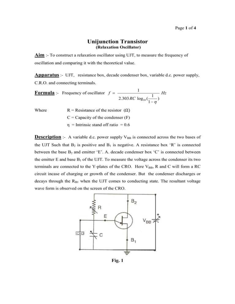
Page 1 of 4 Unijunction Transistor (Relaxation Oscillator) Aim :- To construct a relaxation oscillator using UJT, to measure the frequency of oscillation and comparing it with the theoretical value. Apparatus :- UJT, resistance box, decade condenser box, variable d.c. power supply, C.R.O. and connecting terminals. Formula :- Frequency of oscillator f = Where 1 1 2.303 RC log10 ( ) 1 −η Hz R = Resistance of the resistor (Ω) C = Capacity of the condenser (F) η = Intrinsic stand off ratio = 0.6 Description :- A variable d.c. power supply VBB is connected across the two bases of the UJT Such that B2 is positive and B1 is negative. A resistance box ‘R’ is connected between the base B2 and emitter ‘E’. A. decade condenser box ‘C’ is connected between the emitter E and base B1 of the UJT. To measure the voltage across the condenser its two terminals are connected to the Y-plates of the CRO. Here VBB, R and C will form a RC circuit incase of charging or growth of the condenser. But the condenser discharges or decays through the RB1 when the UJT comes to conducting state. The resultant voltage wave form is observed on the screen of the CRO. Fig. 1 Page 2 of 4 THEORY :- The UJT has negative resistance characteristic, because of this character the UJT provides trigger pulse. Any one of the three terminals can be taken for triggering pulse. The UJT can be used as relaxation oscillator i.e. it produces non-sinusoidal waves. The circuit diagram of relaxation oscillator is as shown in fig. 1. First the capacitor ‘C’ starts charging through the resistor R when VBB is switched on. During the charging of the capacitor, the voltage across it increases exponentially until it reaches to the peak point voltage VP. Up to now, the UJT is in off state, i.e nonconducting state at which RB1 value is high. When the voltage across the capacitor reaches to peak point voltage (VP) then, UJT comes into conducting state as the junction is forward biased and RB1 falls to low value (50Ω). Then the capacitor ‘C’ quickly discharges through UJT that means the discharging time is very less as the capacitor discharges through the low resistance UJT. When the voltage across the capacitor decreases to valley point voltage (VV) then the UJT shifts to off state and once again the capacitor gets charged through the resistor R and this process is repeated. This generates saw-tooth wave form (Fig.2) across the capacitor which can be viewed on the CRO screen. We know in RC circuit the instant charge Multiplying this equation by R\t q = q 0 (1 − e −t / RC ) Rq Rq 0 = (1 − e −t / RC ) t t R I = R I 0 (1 − e − t / RC ) QI=q/t V = V0 (1 − e − t / RC ) ------- (1) Q RI = V This is the general equation for voltage in the charging of a capacitor in RC circuit. But the maximum voltage across the condenser V0 = VBB and V = VP – VB VP − V B = V BB (1 − e −t / RC ) The equation (1) becomes Here, t is the time taken by the condenser to get a charging potential = (VP – VB) ∴ (1 − e −t / RC ) = VP − VB = η Where η is intrinsic stand off ratio. VBB ∴ e −t / RC = (1 −η ) OR ∴ e t / RC = 1 ( 1 −η ) Page 3 of 4 t = RC log e ( 1 ) ------------ (2) 1 −η The time period of the saw tooth wave T = time of charging + time of discharging T = t + td td value is negligibly small When compared to the value of t, as the discharge takes through the low resistance RB1. T≈t --------------- (3) From the equations (2) and (3) the time period of the saw tooth wave 1 ) T = 2.303 RC log10 ( 1 −η or frequency f = 1/T Fig.2 Procedure :- Connect the circuit as shown in Fig. 1 and apply a fixed voltage VBB (5V to 10V) between the two bases B1 and B2. As the Y – plates of CRO is connected across the condenser a saw tooth wave form is observed on its screen when the power is switch on. Adjust of voltage sensitivity band switch of Y-plates and time base band switch X-plates such that at least one or two waves displayed in the screen. Now note the horizontal length(l) between two successive peaks, in the table. When this horizontal length (l) is multiplied by the time base(t) i.e. sec/div , we get the time-period(T).The reciprocal of the time-period(1/T) gives the frequency(f). This is the experimental value. Note the values of resistance R and capacitance C of those connected in the circuit and take the intrinsic stand off ratio η as 0.6, substitute these values in the above formula and find the frequency. This is the theoretical value. Compare the theoretical and Page 4 of 4 experimental frequencies. Repeat the experiment by changing the values of R or C or both. Precautions :- 1) The continuity of the connecting terminals should be checked before going to connect the circuit. 2) Identify the two bases and emitter of UJT and connect properly. 3) The power supply should be ‘on’ only when the observations are taken. 4) Measure the horizontal length of the wave with out any error. Table η = 0.6 Measurement of time period S. R C No. Ω F Horizontal length(l) div. Frequency Time T= base Experimental lxt (t) f= 1/T Sec. sec/div ***** Theoretical f = 1 1 2.303 RC log10 ( ) 1 −η Hz


