Physics 108 Homework #3 Spring 2015 Experiment: RC Circuit
advertisement

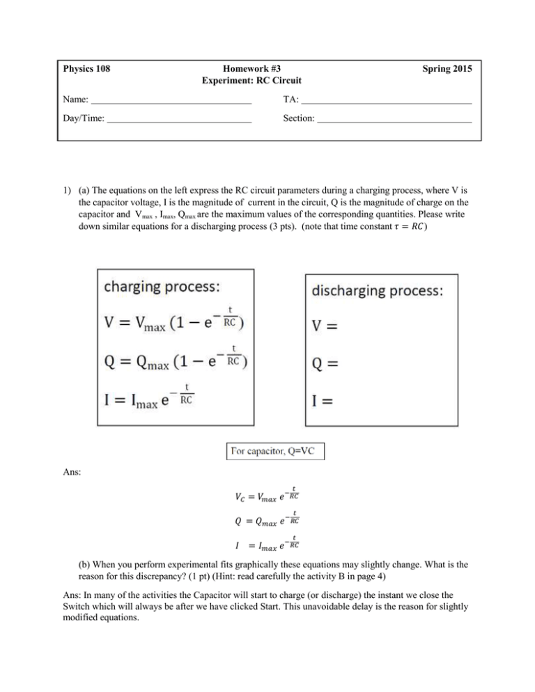
Physics 108 Homework #3 Experiment: RC Circuit Name: TA: Day/Time: Section: Spring 2015 1) (a) The equations on the left express the RC circuit parameters during a charging process, where V is the capacitor voltage, I is the magnitude of current in the circuit, Q is the magnitude of charge on the capacitor and Vmax , Imax, Qmax are the maximum values of the corresponding quantities. Please write down similar equations for a discharging process (3 pts). (note that time constant 𝜏 = 𝑅𝐶) Ans: 𝑡 𝑉𝐶 = 𝑉𝑚𝑎𝑥 𝑒 −𝑅𝐶 𝑡 𝑄 = 𝑄𝑚𝑎𝑥 𝑒 −𝑅𝐶 𝑡 𝐼 = 𝐼𝑚𝑎𝑥 𝑒 −𝑅𝐶 (b) When you perform experimental fits graphically these equations may slightly change. What is the reason for this discrepancy? (1 pt) (Hint: read carefully the activity B in page 4) Ans: In many of the activities the Capacitor will start to charge (or discharge) the instant we close the Switch which will always be after we have clicked Start. This unavoidable delay is the reason for slightly modified equations. 2) Consider the circuit shown below. If the emf voltage of the battery is 20 V, capacitance of the capacitor is 6 µF and the resistance is 2 , a) What will be the time constant of this circuit? (2pts) Ans: time constant 𝜏 = 𝑅𝐶 = 12 𝑢𝑠 b) What will be the voltage difference measured across the capacitor VC if the measurement is made 5 µs after the switch S is closed? (3 pts). Ans: 𝑡 𝑉𝐶 = 𝑉𝑚𝑎𝑥 (1 − 𝑒 −𝑅𝐶 ) = 6.81 𝑉 c) After the switch S is closed, approximately how much time t has to elapse before the voltage across the capacitor VC equals the emf voltage of the battery? (1 pts) (please compare this time with the time constant of this RC circuit (τ)) a) t >>τ b) t <<τ c) 𝑡 ≅τ Ans: Very long time (infinite) has to elapse. t >>τ, ans (a) 2


