Controls Thermal Overload Relays
advertisement

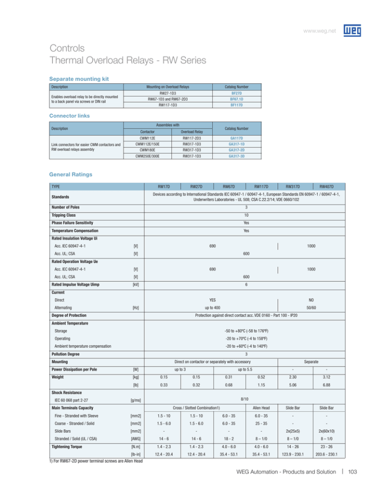
www.weg.net Controls Thermal Overload Relays - RW Series Separate mounting kit Description Enables overload relay to be directly mounted to a back panel via screws or DIN rail Mounting on Overload Relays Catalog Number List Price Multiplier Symbol RW27-1D3 RW67-1D3 and RW67-2D3 RW117-1D3 BF27D BF67.1D BF117D $14 $23 $26 Z2 Z2 Z2 Catalog Number List Price Multiplier Symbol GA117D GA317-1D GA317-2D GA317-3D $41 $68 $70 $118 Z2 Z2 Z2 Z2 Connector links Assembles with Description Link connectors for easier CWM contactors and RW overload relays assembly Contactor Overload Relay CWM112E CWM112E/150E CWM180E CWM250E/300E RW117-2D3 RW317-1D3 RW317-1D3 RW317-1D3 General Ratings TYPE RW17D RW27D RW67D RW117D RW317D RW407D Devices according to International Standards IEC 60947-1 / 60947-4-1, European Standards EN 60947-1 / 60947-4-1, Underwriters Laboratories - UL 508; CSA C.22.2/14; VDE 0660/102 Standards Number of Poles 3 Tripping Class 10 Phase Failure Sensitivity Yes Temperature Compensation Yes Rated Insulation Voltage Ui Acc. IEC 60947-4-1 [V] Acc. UL; CSA [V] 690 1000 600 Rated Operation Voltage Ue Acc. IEC 60947-4-1 [V] Acc. UL; CSA [V] 600 [kV] 6 Rated Impulse Voltage Uimp 690 1000 Current Direct Alternating [Hz] Degree of Protection YES NO up to 400 50/60 Protection against direct contact acc. VDE 0160 - Part 100 - IP20 Ambient Temperature Storage -50 to +80ºC (-58 to 176ºF) Operating -20 to +70ºC (-4 to 158ºF) Ambient temperature compensation -20 to +60ºC (-4 to 140ºF) Pollution Degree 3 Mounting Direct on contactor or separately with accessory Power Dissipation per Pole [W] Weight [kg] 0.15 0.15 0.31 [lb] 0.33 0.32 0.68 up to 3 Separate up to 5.5 - - 0.52 2.30 3.12 1.15 5.06 6.88 Shock Resistance IEC 60 068 part 2-27 8/10 8/10 [g/ms] Main Terminals Capacity Allen Head Slide Bar Slide Bar Fine - Stranded with Sleeve [mm2] 1.5 - 10 1.5 - 10 6.0 - 35 6.0 - 35 - - Coarse - Stranded / Solid [mm2] 1.5 - 6.0 1.5 - 6.0 6.0 - 35 25 - 35 - - Slide Bars [mm2] - - - - 2x(25x5) 2x(60x10) Stranded / Solid (UL / CSA) [AWG] 14 - 6 14 - 6 18 - 2 8 – 1/0 8 – 1/0 8 – 1/0 Tightening Torque Cross / Slotted Combination1) [N.m] 1.4 - 2.3 1.4 - 2.3 4.0 - 6.0 4.0 - 6.0 14 - 26 23 - 26 [lb-in] 12.4 - 20.4 12.4 - 20.4 35.4 - 53.1 35.4 - 53.1 123.9 - 230.1 203.6 - 230.1 1) For RW67-2D power terminal screws are Allen Head WEG Automation - Products and Solution 103 www.weg.net Controls Thermal Overload Relays - RW Series General Ratings TYPE RW17D Front Auxiliary Contact RW27D RW67D RW117D RW317D RW407D 1 NO + 1 NC Rated Auxiliary Contacts AC-14/15 DC-13/14 24V [A] 4.0 60V [A] 3.5 125V [A] 3.0 230V [A] 2.0 400V [A] 1.5 500V [A] 0.5 690V [A] 0.3 24V [A] 1.0 60V [A] 0.5 110V [A] 0.25 220V [A] UL508 0.1 C600 ; R300 Rated Thermal Current [A] 6 [A] 6 Fine - Stranded with Sleeve [mm2] 1.0 - 2.5 Coarse - Stranded / Solid [mm2] 1.0 - 2.5 Stranded / Solid (UL / CSA) [AWG] 16 - 12 [N.m] 1.0 - 1.5 [lb-in] 8.9 - 13.3 Short Circuit Protection Fuses Type D or NH gL/gG Auxiliar Terminals Capacity Tightening Torque NOTE: The derating of a RW overload relay has two possible factors: 1) Ambient temperature • Temperature compensation considers a factor according to which the rated current must be reduced when ambient temperature is higher than 60ºC (140ºF). 2) Altitude • Altitude compensation involves both, rated current and voltage. •C urrent compensation considers a factor according to the rated current must be reduced. • For voltage, altitude limits the higher operating voltage we can use the overload relay. The derating of the permissible operating current for installation altitudes above 2,000m (6,667 ft) and ambient temperatures over 60ºC (140ºF) is calculated according to: Total derating = Derating altitude x Derating ambient temperature Example; Altitude: 3,000 m (10,000 ft) Ambient temperature: 70ºC (158ºF) Meters Total current derating = 0.96 x 0.87 = 0.84 x Ie In this case, the maximum rated voltage we can connect to our RW overload relay is 550V. Derating Factor In order to select the proper overload relay, you have to choose a device with a current range that accommodates: Overload Setting Point = FLAmotor / (K1 x K2) As in the example above, K1 x K2 = 0.84 For a motor with FLA = 20Amps Overload Setting Point = 20 / 0.84 = 23.8Amps 104 1-800-ASK-4WEG K1 = 0.96 K2 = 0.87

