Lecture Notes on RC Circuits - University of Colorado Boulder
advertisement

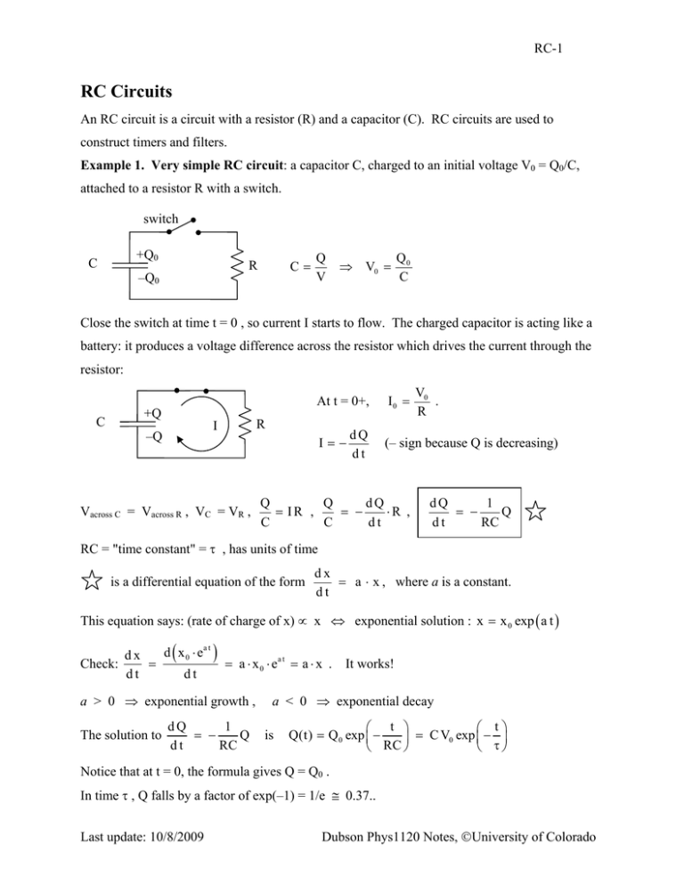
RC-1 RC Circuits An RC circuit is a circuit with a resistor (R) and a capacitor (C). RC circuits are used to construct timers and filters. Example 1. Very simple RC circuit: a capacitor C, charged to an initial voltage V0 = Q0/C, attached to a resistor R with a switch. switch +Q0 C C= R –Q0 Q V ⇒ V0 = Q0 C Close the switch at time t = 0 , so current I starts to flow. The charged capacitor is acting like a battery: it produces a voltage difference across the resistor which drives the current through the resistor: At t = 0+, C +Q I –Q R I=− Vacross C = Vacross R , VC = VR , dQ dt I0 = V0 . R (– sign because Q is decreasing) Q Q dQ = IR , = − ⋅R , C C dt dQ 1 = − Q dt RC RC = "time constant" = τ , has units of time is a differential equation of the form dx = a ⋅ x , where a is a constant. dt This equation says: (rate of charge of x) ∝ x ⇔ exponential solution : x = x 0 exp ( a t ) d ( x 0 ⋅ ea t ) dx Check: = = a ⋅ x 0 ⋅ ea t = a ⋅ x . dt dt a > 0 ⇒ exponential growth , The solution to dQ 1 = − Q dt RC It works! a < 0 ⇒ exponential decay is ⎛ t ⎞ ⎛ t⎞ Q(t) = Q 0 exp ⎜ − ⎟ = C V0 exp ⎜ − ⎟ ⎝ RC ⎠ ⎝ τ⎠ Notice that at t = 0, the formula gives Q = Q0 . In time τ , Q falls by a factor of exp(–1) = 1/e ≅ 0.37.. Last update: 10/8/2009 Dubson Phys1120 Notes, ©University of Colorado RC-2 In time 2τ, Q falls by a factor of exp(–2) = (1/e)(1/e) ≅ 0.14.. ⇒ Q approaches zero asymptotically, and so does V and I Q ⎛ t ⎞ ⎛ t⎞ Q(t) = Q 0 exp ⎜ − ⎟ = Q 0 exp ⎜ − ⎟ ⎝ RC ⎠ ⎝ τ⎠ Q0 Q0/e t τ I =− V=Q/C V dQ = + 0 exp(− t / τ) dt R t t Example 2: More complex RC circuit: Charging a capacitor with a battery. switch E C VC = Q / C Let's use symbol E for battery voltage (E short for emf) because there are so many other V's in this example. Before switch is closed, I = 0, Q = 0. R VR = I R Close switch at t = 0. Always true that E = VC + VR , by Kirchhoff's Voltage Law (Loop Law) The charge Q on the capacitor and the voltage VC = Q / C across the capacitor cannot change instantly, since it takes time for Q to build up, so .. At t = 0+ , Q = 0 , VC = 0, E = VC + VR = VR = I R ⇒ I0 = E / R Although Q on the capacitor cannot change instantly, the current I = dQ/dt can change instantly. "Current through a capacitor" means dQ/dt . Even though there is no charge ever passing between the plates of the capacitor, there is a current going into one Last update: 10/8/2009 + - I + + + Dubson Phys1120 Notes, ©University of Colorado I RC-3 plate and the same current is coming out of the other plate, so it is as if there is a current passing through the capacitor. C E E = VR + VC Q C E = IR + I R E = , I=+ dQ dt dQ Q R + dt C Qualitatively, as t ↑ , Q ↑ , VC = Q/C ↑ , VR ↓ , I = VR / R ↓. After a long time , t >> τ = RC , the current decreases to zero: I = 0, VC = E , Q = C E Vc = Q / C Analytic solution: E VC (t) = E [1 − exp(− t / RC) ] Q(t) = E ⋅ C [1 − exp( − t / RC) ] t Things to remember: • Uncharged capacitor acts like a "short" ( a wire ) since VC = Q / C = 0. • After a long time, when the capacitor is fully charged, it acts like an "open-circuit" ( a break the wire). We must have IC = 0 eventually, otherwise Q → ∞ , VC → ∞ . Last update: 10/8/2009 Dubson Phys1120 Notes, ©University of Colorado


