60 watt Incandescent Bulb Characteristics
advertisement

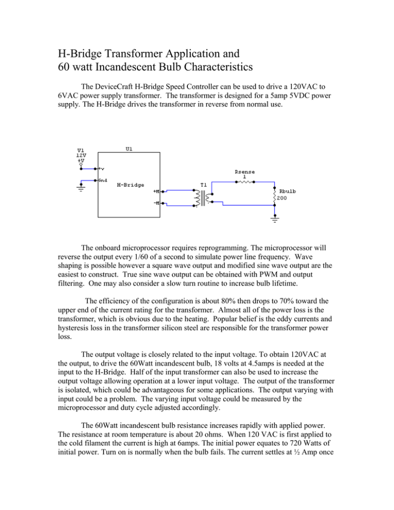
H-Bridge Transformer Application and 60 watt Incandescent Bulb Characteristics The DeviceCraft H-Bridge Speed Controller can be used to drive a 120VAC to 6VAC power supply transformer. The transformer is designed for a 5amp 5VDC power supply. The H-Bridge drives the transformer in reverse from normal use. The onboard microprocessor requires reprogramming. The microprocessor will reverse the output every 1/60 of a second to simulate power line frequency. Wave shaping is possible however a square wave output and modified sine wave output are the easiest to construct. True sine wave output can be obtained with PWM and output filtering. One may also consider a slow turn routine to increase bulb lifetime. The efficiency of the configuration is about 80% then drops to 70% toward the upper end of the current rating for the transformer. Almost all of the power loss is the transformer, which is obvious due to the heating. Popular belief is the eddy currents and hysteresis loss in the transformer silicon steel are responsible for the transformer power loss. The output voltage is closely related to the input voltage. To obtain 120VAC at the output, to drive the 60Watt incandescent bulb, 18 volts at 4.5amps is needed at the input to the H-Bridge. Half of the input transformer can also be used to increase the output voltage allowing operation at a lower input voltage. The output of the transformer is isolated, which could be advantageous for some applications. The output varying with input could be a problem. The varying input voltage could be measured by the microprocessor and duty cycle adjusted accordingly. The 60Watt incandescent bulb resistance increases rapidly with applied power. The resistance at room temperature is about 20 ohms. When 120 VAC is first applied to the cold filament the current is high at 6amps. The initial power equates to 720 Watts of initial power. Turn on is normally when the bulb fails. The current settles at ½ Amp once the bulb is heated. One question would be, if the bulb turned on slowly how many ON cycles could the handle verse normal switching? The visible light output verses power would also be interesting measurement. At 20 Watts almost no light is visible. Could the 60-Watt bulb be operated at 100 Watts or more? How would the lifetime be effected? The large transformer is also a drawback. The tested transformer is about 4inches long, 3 inches wide, 3 inches high, and weighs about 5 pounds. Linear power supplies used similar transformers however they are large and heavy. Switching power supplies do not use 50/60Hz transformers on the inputs. The switching power supplies are smaller, lighter, and more efficient. Switching power supplies use ferrite or iron core material for the inductor/transform. The ferrite and iron core have significantly lower losses. The large 50/60 Hz transformers could be replaced with a smaller powered iron core type. The powered iron core transform will have a lower inductance and need to be operated at a higher frequency. Vrms Amps Resistance Power Watts 0.63 0.032 19.69 0.02016 2 0.079 25.32 0.158 4.5 0.115 39.13 0.5175 9.7 0.15 64.67 1.455 11.46 0.16 71.63 1.8336 19.7 0.2 98.50 3.94 43.7 0.29 150.69 12.673 60.4 0.35 172.57 21.14 82.7 0.414 199.76 34.2378 97 0.45 215.56 43.65 109 0.48 227.08 52.32 124.6 0.515 241.94 64.169 140 0.547 255.94 76.58 157 0.584 268.84 91.688 170 0.61 278.69 103.7 60 Watt Bulb Resistance Vs. Voltage 300.00 Resistance Ohms 250.00 200.00 150.00 100.00 50.00 0.00 0 50 100 Volta ge Vrm s 150 200 60 Watt Bulb Current Vs. Voltage 0.7 Current Amps 0.6 0.5 0.4 0.3 0.2 0.1 0 0 50 100 150 200 150 200 Volta ge Vrm s 60 Watt Bulb Power Vs. Voltage 120 Power Watts 100 80 60 40 20 0 0 50 100 Volta ge Vrm s

