LEP 4.4.10 RLC measuring bridge
advertisement

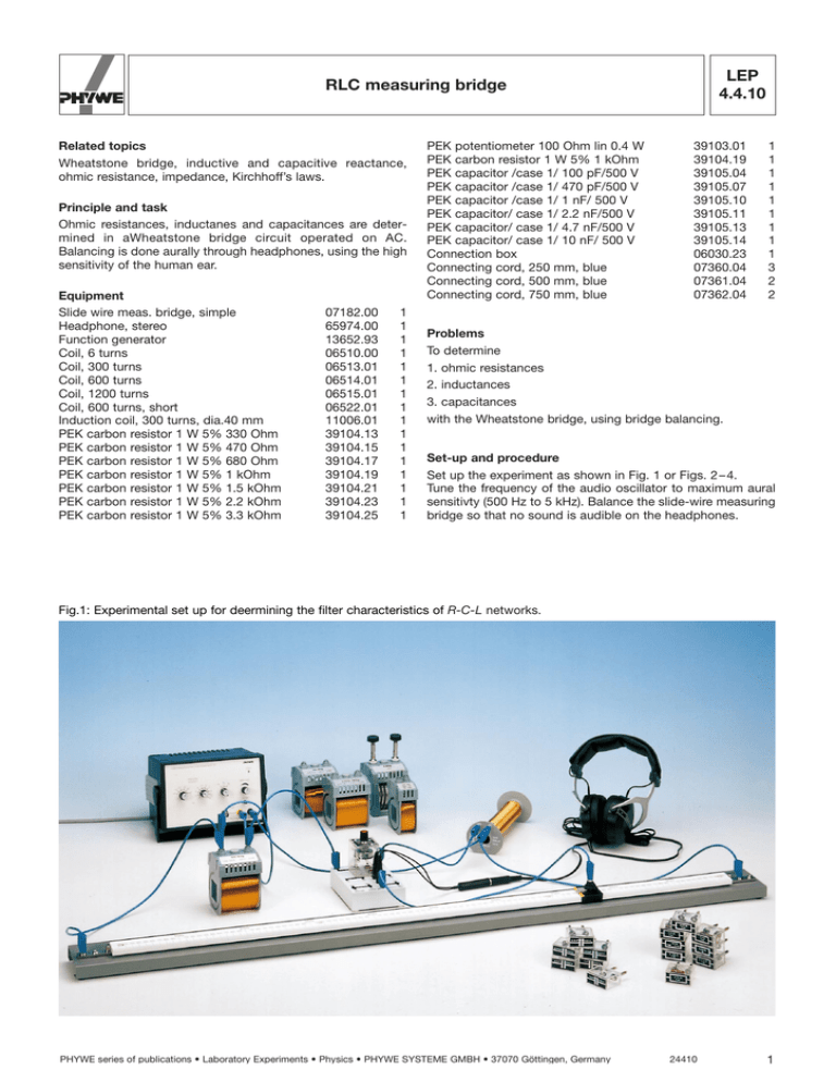
R LEP 4.4.10 RLC measuring bridge Related topics Wheatstone bridge, inductive and capacitive reactance, ohmic resistance, impedance, Kirchhoff’s laws. Principle and task Ohmic resistances, inductanes and capacitances are determined in aWheatstone bridge circuit operated on AC. Balancing is done aurally through headphones, using the high sensitivity of the human ear. Equipment Slide wire meas. bridge, simple Headphone, stereo Function generator Coil, 6 turns Coil, 300 turns Coil, 600 turns Coil, 1200 turns Coil, 600 turns, short Induction coil, 300 turns, dia.40 mm PEK carbon resistor 1 W 5% 330 Ohm PEK carbon resistor 1 W 5% 470 Ohm PEK carbon resistor 1 W 5% 680 Ohm PEK carbon resistor 1 W 5% 1 kOhm PEK carbon resistor 1 W 5% 1.5 kOhm PEK carbon resistor 1 W 5% 2.2 kOhm PEK carbon resistor 1 W 5% 3.3 kOhm 07182.00 65974.00 13652.93 06510.00 06513.01 06514.01 06515.01 06522.01 11006.01 39104.13 39104.15 39104.17 39104.19 39104.21 39104.23 39104.25 1 1 1 1 1 1 1 1 1 1 1 1 1 1 1 1 PEK potentiometer 100 Ohm lin 0.4 W PEK carbon resistor 1 W 5% 1 kOhm PEK capacitor /case 1/ 100 pF/500 V PEK capacitor /case 1/ 470 pF/500 V PEK capacitor /case 1/ 1 nF/ 500 V PEK capacitor/ case 1/ 2.2 nF/500 V PEK capacitor/ case 1/ 4.7 nF/500 V PEK capacitor/ case 1/ 10 nF/ 500 V Connection box Connecting cord, 250 mm, blue Connecting cord, 500 mm, blue Connecting cord, 750 mm, blue 39103.01 39104.19 39105.04 39105.07 39105.10 39105.11 39105.13 39105.14 06030.23 07360.04 07361.04 07362.04 1 1 1 1 1 1 1 1 1 3 2 2 Problems To determine 1. ohmic resistances 2. inductances 3. capacitances with the Wheatstone bridge, using bridge balancing. Set-up and procedure Set up the experiment as shown in Fig. 1 or Figs. 2 – 4. Tune the frequency of the audio oscillator to maximum aural sensitivty (500 Hz to 5 kHz). Balance the slide-wire measuring bridge so that no sound is audible on the headphones. Fig.1: Experimental set up for deermining the filter characteristics of R-C-L networks. PHYWE series of publications • Laboratory Experiments • Physics • PHYWE SYSTEME GMBH • 37070 Göttingen, Germany 24410 1 R LEP 4.4.10 RLC measuring bridge 1. Fig. 5: Wheatstone bridge. Fig. 2: Circuit for measuring resistance. 2. Potentiometer, P1 is needed to compensate for the different d. c. resistances in the coils when determining inductive reactance. The low resistance generator output is used here to obtain better matching. Theory and evaluation From Kirchhoff’s laws we obtain the condition for brige balancing which relates to the general bridge construction in Fig. 5 with the unknown impedance Z3 and the reference impedance Z4. The current IB in the shunt branch is zero, IB = 0 (1) R1 Z3 = R2 Z4 (2) when Fig. 3: Circuit for measuring inductances. In complex notation, the general form of the impedance Z is ( Z = R + i vL – Now move both slides in each direction until you find a position at which the sound disappears. 1 vC ) (3) where i = √-1, v = 2 pƒ, and ƒ is the frequency of the applied voltage. 3. Substituting in (2) gives R1 5 R2 ( vC1 ) 1 1 i (vL vC ) R3 1 i vL3 R4 3 4 (4) 4 The real and imaginary components must agree on both sides, so that we obtain two conditions: Amplitude condition: R1 5 R2 Fig. 4: Circuit for measuring capacitances. 2 24410 1 1 vL4 – vC3 vC4 1 2 R42 1 vL4 – vC4 ( R3R4 1 vL3 – ( )( ) ) (5) PHYWE series of publications • Laboratory Experiments • Physics • PHYWE SYSTEME GMBH • 37070 Göttingen, Germany R LEP 4.4.10 RLC measuring bridge and phase condiction: ( R4 vL3 – 1 1 = R3 vL4 – vC3 vC4 ) ( ) (6) The inductance of the reference coil (Cat. No. 11006.01) is determined from its dimensions (Kohlrausch, Praktische Physik [Practical Physics[, Vol. 2): L4 = 2.1 · 10-6 · N2 · r · To fulfil (6), Z3 and Z4 must consist of like components. ( rl ) 3/4 where L is in henrys, radius r and length ι are in metres, and N is the number of turns. 1. Ohmic resistances Z3 = R3, Z4 = R4 When N = 300, l = 0.16 m and r = 0.02 m we obtain In this case, (2) simplifies to L4 = 795 µH R1 R3 = R2 R4 Coil (Cat. No.) 06515.00 06512.00 06522.00 06514.00 06513.00 The ratio R1/R2 is given by the length k and the total length i of the slide wire (Fig. 2). We thus obtain the unknown resistance R3 = R4 x l– x (7) The following average volues are obtained from the measurements when R4 = l kΩ and l = 100 cm: Resistor (Cat. No.) 39104.12 39104.15 39104.17 39104.19 39104.21 39104.23 39104.25 | | | | | | | | | x cm 21.3 28.4 45.05 54.5 60.5 68.85 73.4 | | | | | | | | | R3 Ω 271 397 820 1200 1530 2210 2760 2. Inductances Besides an inductive resistance, coils also have an ohmic reasctance x cm 98.0 96.6 94.8 92.4 75.0 L3 mH 39.0 22.6 14.5 9.7 2.39 | | | | | | | 3. Capacitances When Z3 = – i vC3 Z4 = – i vC4 (6) is fulfilled and we obtain R1 C4 = R2 C3 thus C3 = C4 Z3 = R3 + ivL3 | | | | | | | l–x x (10) Z4 = R4 + ivL3 When C4 = 100 pF we obtain the following measured values: From (6) we first obtain R1 L3 = R2 L4 (8) In order to be able to fulfil this condiction we have also to connect a potentiometer into also to connect a potentiometer into the bridge branch with the coils (Fig. 3). R3 or R4 is then the sum of the potentiometer component and the ohmic resistance of the coil in the corresponding branch. Capacitor (Cat. No.) 39105.14 39105.13 39105.11 39105.10 39105.07 39105.04 | | | | | | | | x cm 9.0 17.9 32.1 50.1 68.2 91.1 C3 nF 10 4.6 2.12 0.98 0.466 0.097 | | | | | | | | Substitutin (8) into (5) we obtain R1 L3 = R2 L4 so that L3 = L4 x l– x (9) PHYWE series of publications • Laboratory Experiments • Physics • PHYWE SYSTEME GMBH • 37070 Göttingen, Germany 24410 3


