Eliminating Filter Bypass Contactor in Offline Drive Applications
advertisement

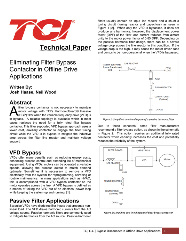
Technical Paper filters usually contain an input line reactor and a shunt a tuning circuit (tuning reactor and capacitors) as seen in Figure 1 [2]. When only the VFD is bypassed, it does not produce any harmonics, however, the displacement power factor (DPF) of the filter load current reduces from almost unity to the motor power factor of 0.85 DPF. Depending on the passive harmonic filter design, there can be a severe voltage drop across the line reactor in this condition. If the voltage drop is too high, it may cause the motor driven fans and pumps to be non-operational when the VFD is bypassed. Eliminating Filter Bypass Contactor in Offline Drive Applications Written By: Josh Haase, Neil Wood Abstract A filter bypass contactor is not necessary to maintain motor voltage with TCI’s HarmonicGuard® Passive (HGP) filter when the variable frequency drive (VFD) is in bypass. A reliable topology is available which in most cases replaces the need for a fully rated filter bypass contactor. This filter supported VFD bypass approach uses a lower cost, auxiliary contactor to engage the filter tuning circuit while the VFD is in bypass to mitigate the inductive drop across the filter line reactor and maintain voltage support. Figure 1: Simplified one-line diagram of a passive harmonic filter Due to these concerns, some filter manufacturers recommend a filter bypass option, as shown in the schematic in Figure 2. This option requires an additional fully rated contactor which certainly increases the cost and potentially reduces the reliability of the system. VFD Bypass VFDs offer many benefits such as reducing energy costs, enhancing process control and extending life of mechanical equipment. Using VFDs, motors can be operated at variable speeds, allowing the process output to match demand optimally. Sometimes it is necessary to remove a VFD electrically from the system for reprogramming, servicing or routine maintenance. In many applications such as HVAC, this is accomplished with a VFD bypass contactor so the motor operates across the line. A VFD bypass is defined as a means of taking the VFD out of an electrical power loop while keeping the system up and running. [1]. Passive Filter Applications Six pulse VFDs have diode rectifier inputs that present a nonlinear load. The VFD draws harmonic currents from the AC voltage source. Passive harmonic filters are commonly used to mitigate harmonics from the AC source. Passive harmonic Figure 2: Simplified one-line diagram of filter bypass contactor TCI, LLC | Bypass Disconnect in Offline Drive Applications 1 TCI’s HGP filter design offers an alternative approach that eliminates the need to bypass the filter when the VFD is bypassed, while maintaining nominal rms voltage to the motor. HGP with VFD in bypass Motor Voltage (V) Due to the HGP’s tuning circuit design, there is only a 3.5% max voltage deviation from nominal 480V rms systems as seen in Figure 3. The capacitors in the HGP tuning circuit provide voltage support. 505 495 485 475 Many passive filters have trap contactors in series with the trap circuit to disengage the tuning circuit at light loads and when the drive is off. In this case, it is critical to engage the trap contactor when the VFD is in bypass to maintain voltage support. This can be achieved using a small auxiliary contact on the VFD bypass contactor that pulls in the trap contactor engaged when the VFD is in bypass. Some passive filter designs rely on oversized line reactor impedance to minimize tuning circuit capacitance cost or accommodate some other design concession. For those products the voltage drop in bypass will be so great the only alternative is to add a fully rated contactor to bypass the filter instead of the lower cost filter supported VFD bypass approach outlined above. All TCI passive filter designs support the lower cost filter supported VFD bypass approach outlined in this whitepaper. 465 455 20% 40% 60% 80% 100% Load VFD bypass without HGP filter bypass 480V Reference +5% Motor Supply Voltage -5% Motor Supply Voltage Figure 3: Motor Voltage under different VFD bypass configurations Motors are designed to operate with a supply voltage within ±5% of nominal voltage. The voltage support provided by the HGP capacitors limits the drop in output voltage to 3.5%. Additionally, the capacitors provide power factor correction while the drive is bypassed, improving the source power factor as seen in Figure 4. 1.1 1 Conclusion Bypass disconnect contactors are an added expense when it comes to taking a passive filter and drive out of a power system. TCI’s HGP allows a customer to leave the filter online while disconnecting the VFD. It is a cost effective option and provides better input power factor correction from the capacitors. The motor input voltage is still fully operational providing the customer protection from harmful voltage drops from added impedance in the power system. References [1] “VFD Electronic Bypass Benefits”, Siemens Building Technologies. http://www.achrnews.com/articles/91703-vfd-electronicbypass-benefits [2] “Generator Compatibility of Passive Filters”, Wallace. http://www.transcoil.com/Public/Documents/TechnicalPaper s/Generator-Compatibility-Passive-Filters.pdf PF 0.9 0.8 0.7 0.6 0.5 20% 40% 60% 80% 100% Load VFD bypass without HGP filter bypass VFD bypass with HGP filter bypass Figure 4: Input PF under different VFD bypass configurations TCI, LLC | Bypass Disconnect in Offline Drive Applications TCI, LLC W132 N10611 Grant Drive Germantown, WI 53022 (414) 357-4480 FAX (414) 357-4484 PQ Helpline (800) TCI-8282 www.transcoil.com 2


