Timers Application Notes
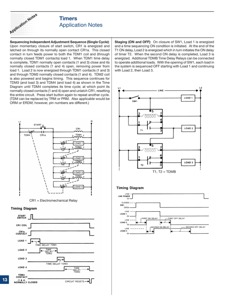
advertisement

s te o nN c pli Ap io at Timers Application Notes Sequencing Independent Adjustment Sequence (Single Cycle): Upon momentary closure of start switch, CR1 is energized and latched on through its normally open contact CR1a. This closed contact in turn feeds power to both the TDM1 coil and (through normally closed TDM1 contacts) load 1. When TDM1 time delay is complete, TDM1 normally open contacts (1 and 3) close and its normally closed contacts (1 and 4) open, removing power from load 1. Load 2 is now energized through TDM1 contacts (1 and 3) and through TDM2 normally closed contacts (1 and 4). TDM2 coil is also powered and begins timing. This sequence continues for TDM3 (and load 3) and TDM4 (and load 4) as shown in the Time Diagram until TDM4 completes its time cycle; at which point its normally closed contacts (1 and 4) open and unlatch CR1, resetting the entire circuit. Press start button again to repeat another cycle. (TDM can be replaced by TRM or PRM. Also applicable would be ORM or ERDM; however, pin numbers are different.) Staging (ON and OFF): On closure of SW1, Load 1 is energized and a time sequencing ON condition is initiated. At the end of the T1 ON delay, Load 2 is energized which in turn initiates the ON delay of timer T2. When the second ON delay is completed, Load 3 is energized. Additional TDMB Time Delay Relays can be connected to operate additional loads. With the opening of SW1, each load in the system is sequenced OFF starting with Load 1 and continuing with Load 2, then Load 3. T1, T2 = TDMB CR1 = Electromechanical Relay Ap pli Timers Application Notes Dual Momentary Timing (With Lockout): Both timing circuits are of the single shot type. Because of the normally closed contacts in series with each push-button, one circuit is disabled when the other is in use. ca tio nN ot es Plug-in Timers: The three-wire PS will operate with all plug-in timers as shown in Figures 1A and 1B. Two-wire proximity devices have minimum load requirements. The load resistor Rd shown in Figure 2 & 3 is necessary for proper operation of the proximity device. See proximity data sheets for correct load values. Figure 2 TDB, TRB, TDS, TRS Figure 3 TDM, TRM, TDR, TDI Pulse Shaping: (Fig. 3) For pulse shaping applications, the timer coil is wired in series with the PS. Resistor Rd may be required for proper operation of the PS. T1 and T2 = TS2, TS4, TSD2, TSD4, Also see ORS and ERDI Solid State Timers: The three-wire PS can be wired directly to most solid state timers as shown in Figures 4A through 4D. Using Proximity and Photoelectric Switches with Timers The Characteristics of Proximity and Photoelectric Switches, also known as solid state electric switches can successfully be used with timers. Typically, a two-wire proximity or photoelectric switch will leak approximately 2.5 milliamperes of current when in its OFF state. The three-wire proximity and photoelectric switches exhibit little, if any, leakage current. The following circuits show the various interfacing of proximity or photoelectric switches (PS) with timers. Figure 1A TRS, TDS, TRB, TDB Figure 1B TRM, TDM, TDI, TDR Figure 4A TS1, TSD1, TDU, KSDI, TSU2000, TMV8000 Figure 4C TSDS, TSDB Figure 4B TS2, TSD2, TSDR, TSD3, KSD2, KSDR Figure 4D RS Series s te o nN c pli Ap Timers Application Notes io at Solid State Timers (continued from previous page): In some applications, an interfacing device may be required as shown in Figure 5. A simple relay interface would provide the dry closure required by this series of timers. Note: This same principle can be used with the two-wire PS. Timers TS2 and the TSDR Series do not require a shunt resistor and can be operated efficiently with two-wire PS as shown in Fig. 8. Be aware that the application of a two-wire PS with solid state timers is varied. If you do not find your application in these notes, contact our Technical Assistance Department about your specific requirements. Figure 8 TS2, TSDR Figure 5 TSB, TSS Leakage Current: (Control of) Solid state switches have an ON resistance of about 5 to 10 ohms and an OFF resistance of a few hundred thousand ohms causing a certain amount of leakage through the solid state switch during the OFF state. This leakage can present problems. The leakage current of the two-wire type PS may result in premature timing of the two-terminal solid state timers. This leakage current can be redirected by using a shunt resistor Rs as shown in Figures 6 and 7. Possible Shunt Resistor Values (Rs) Voltage 24VAC 24VAC 24VAC 120VAC 120VAC 120VAC 240VAC 240VAC 240VAC Value in Ohms 100 270 470 2,500 5,000 10,000 6,000 10,000 27,000 Power in Watts NOTE: Due to a number of variables, we urge you to consult our Technical Assistance group or that of the switch manufacturer. Rs = 10K, 2W at 120VAC Figure 6 TSD2, TSD3 Rs = 2.5K, 10W at 120VAC Figure 7 TS1, TSD1, TDU, TMV8000, TSU2000 7 3 2 10 5 2 10 7 3 Timers Application Notes Random Start: Random start timing is a common practice used to prevent overloading of power lines and the reducing of peak demand levels. In industrial and commercial locations where numbers of compressors are used for air conditioning, heating, refrigeration, compressed air, and electric heating elements are used to heat air, water, or in process equipment, it is important that all of this equipment not start at the same time. This can happen in the case of a power failure or with night shutoff systems. If simultaneous starting is allowed, damage can occur due to low voltage starts. One way to correct this situation is to provide a Random Start system. This is accomplished by placing a timer in each piece of equipment to delay start. These timers are set at different times so that a staggered or random start situation is achieved. NOTE: Also see TMV8000 and TSU2000 Thermistor Controlled Timer: This application utilizes a negative temperature coefficient (NTC) thermistor to change the time delay as a function of temperature. NTC thermistors decrease in resistance as temperature increases. In this case, the OFF time is being varied. As the temperature increases, the cycles per minute increase as a result of a shorter OFF time. TSDR445SA0 Ap pli ca tio nN ot es Part Winding Start: The following is a typical wiring diagram for reduced torque starting of a 2 winding, 3 phase motor. Upon closure of the Start button, 1MC is energized and TAC1 begins its time delay. At the end of TAC1’s time delay, 2MC is energized. The circuit is reset upon opening of Stop button or O.L. contact. s te o nN c pli Ap io at Timers Application Notes Air Compressor Drain, Automatic Operation: Upon application of power, the external adjustable 1 to 100 minutes OFF time delay begins. At the end of the OFF period, a fixed ON time of 2 seconds is initiated which energizes the solenoid, and drains the condensation commonly built up in a compressor. OFF/ON recycling continues until the input power is removed. The KSPD and ESDR Series are also available featuring onboard or remotely adjustable ON and OFF time delay control. Timers Application Notes Flow Monitor (Delay on Make Normally Closed): Flow monitoring is used in industrial applications where a continual flow of product is necessary, and can terminate the operation if the flow is not detected. Upon closure of SW1, T1 time delay is initiated and relay CR is energized. When the normally open contacts of relay CR close, energizing the pump, the resulting flow (Int. #1) opens flow switch SW2. Each time SW2 opens, T1 time delay is set to zero. (Int. #2) As long as SW2 remains open, timing will not progress. Should the SW2 flow switch close and re-open before the end of the T1 time delay, the pump will stay energized. When the flow switch SW2 closes and remains closed for a period longer than the T1 time delay (Int. #3), T1 de-energizes the control relay and disconnects the pump. To reset, open SW1. Ap pli ca tio nN ot es Motion Detectors, Zero Speed Switch a Low Cost Approach Many conveyor systems use a logic control module as an interface between the proximity or photoelectric switch and its associated load. The KRD9, KRPS, KSPS, NHPS, HRD9, TRDU, and TRU series of low cost Timers/Controls (retriggerable single shot function) are designed to detect motion and/or zero speed by monitoring the pulses from an external photoelectric or proximity switch. These pulses continuously reset the control’s timing circuit, preventing it from completing its selected time delay. If a pulse is missing, the control completes its time delay and the output changes state. To operate correctly, 2-wire proximity and photoelectric switches require a “leakage” or “residual” current flow during their OFF state. See Application Notes: Leakage Current (Control of) for possible (shunt) limit resistor values table. In the diagram shown, the conveyor motor (CR1) starts when SW1 start switch closes. The conveyor establishes the pulse train which is sensed by SW2, a two wire photo switch. Each time an object is sensed by SW2, it resets the timing circuit of the timer and the conveyor continues to run. If SW2 stops sensing moving objects, (the pulses are interrupted), the timer completes its time delay and de-energizes the conveyor contactor coil (CR1). The N.C. stop switch immediately turns OFF the conveyor when it opens. T1 = TSD4, THD4, KSD4 Pump Control: Upon closure of float switch, FS1, the delay on make time delay is initiated. This time delay will be reset if the float switch does not stay closed for the duration of the ON delay. At the end of the ON time delay, the pump motor is energized and will remain in this condition if no further action is taken. When the float switch opens, the motor stays running for the length of the delay on break time delay, then shuts off. Should the FS1 be reclosed during the delay on break period, the OFF delay will reset to zero. T1 = TDMB Our line of Motion Detectors/Zero Speed Switches/Retriggerable Single Shot Timers are designed for use in conveyor, elevator, escalator, and process control applications. They are available in encapsulated or un-encapsulated versions, and with solid state or relay outputs.


