High precision Watt Meter and Power Analyzer
advertisement

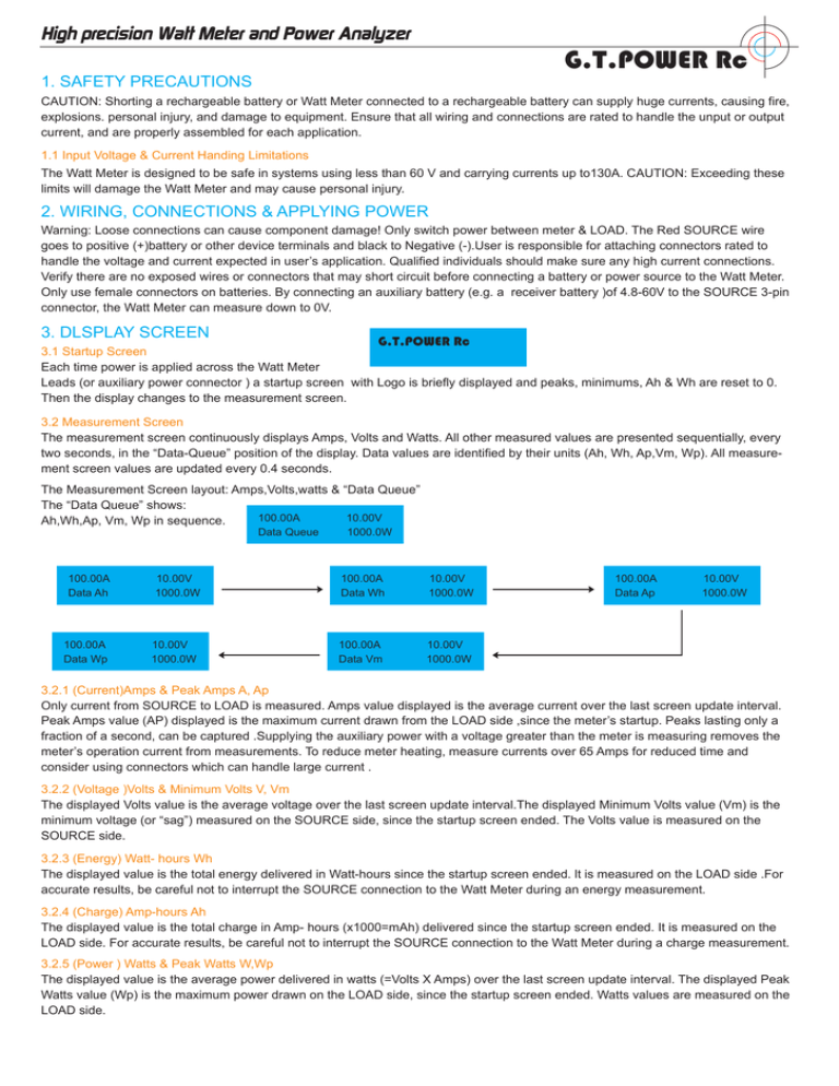
High precision Watt Meter and Power Analyzer G.T.POWER Rc 1. SAFETY PRECAUTIONS CAUTION: Shorting a rechargeable battery or Watt Meter connected to a rechargeable battery can supply huge currents, causing fire, explosions. personal injury, and damage to equipment. Ensure that all wiring and connections are rated to handle the unput or output current, and are properly assembled for each application. 1.1 Input Voltage & Current Handing Limitations The Watt Meter is designed to be safe in systems using less than 60 V and carrying currents up to130A. CAUTION: Exceeding these limits will damage the Watt Meter and may cause personal injury. 2. WIRING, CONNECTIONS & APPLYING POWER Warning: Loose connections can cause component damage! Only switch power between meter & LOAD. The Red SOURCE wire goes to positive (+)battery or other device terminals and black to Negative (-).User is responsible for attaching connectors rated to handle the voltage and current expected in user’s application. Qualified individuals should make sure any high current connections. Verify there are no exposed wires or connectors that may short circuit before connecting a battery or power source to the Watt Meter. Only use female connectors on batteries. By connecting an auxiliary battery (e.g. a receiver battery )of 4.8-60V to the SOURCE 3-pin connector, the Watt Meter can measure down to 0V. 3. DLSPLAY SCREEN G.T.POWER Rc 3.1 Startup Screen Each time power is applied across the Watt Meter Leads (or auxiliary power connector ) a startup screen with Logo is briefly displayed and peaks, minimums, Ah & Wh are reset to 0. Then the display changes to the measurement screen. 3.2 Measurement Screen The measurement screen continuously displays Amps, Volts and Watts. All other measured values are presented sequentially, every two seconds, in the “Data-Queue” position of the display. Data values are identified by their units (Ah, Wh, Ap,Vm, Wp). All measurement screen values are updated every 0.4 seconds. The Measurement Screen layout: Amps,Volts,watts & “Data Queue” The “Data Queue” shows: 100.00A 10.00V Ah,Wh,Ap, Vm, Wp in sequence. Data Queue 100.00A Data Ah 100.00A Data Wp 10.00V 1000.0W 10.00V 1000.0W 1000.0W 100.00A Data Wh 10.00V 1000.0W 100.00A Data Vm 10.00V 1000.0W 100.00A Data Ap 10.00V 1000.0W 3.2.1 (Current)Amps & Peak Amps A, Ap Only current from SOURCE to LOAD is measured. Amps value displayed is the average current over the last screen update interval. Peak Amps value (AP) displayed is the maximum current drawn from the LOAD side ,since the meter’s startup. Peaks lasting only a fraction of a second, can be captured .Supplying the auxiliary power with a voltage greater than the meter is measuring removes the meter’s operation current from measurements. To reduce meter heating, measure currents over 65 Amps for reduced time and consider using connectors which can handle large current . 3.2.2 (Voltage )Volts & Minimum Volts V, Vm The displayed Volts value is the average voltage over the last screen update interval.The displayed Minimum Volts value (Vm) is the minimum voltage (or “sag”) measured on the SOURCE side, since the startup screen ended. The Volts value is measured on the SOURCE side. 3.2.3 (Energy) Watt- hours Wh The displayed value is the total energy delivered in Watt-hours since the startup screen ended. lt is measured on the LOAD side .For accurate results, be careful not to interrupt the SOURCE connection to the Watt Meter during an energy measurement. 3.2.4 (Charge) Amp-hours Ah The displayed value is the total charge in Amp- hours (x1000=mAh) delivered since the startup screen ended. It is measured on the LOAD side. For accurate results, be careful not to interrupt the SOURCE connection to the Watt Meter during a charge measurement. 3.2.5 (Power ) Watts & Peak Watts W,Wp The displayed value is the average power delivered in watts (=Volts X Amps) over the last screen update interval. The displayed Peak Watts value (Wp) is the maximum power drawn on the LOAD side, since the startup screen ended. Watts values are measured on the LOAD side. 4. BUSING Watt Meter You can think of the Watt Meter as a set of jumper wires. Connect it in the same way and you can measure what the jumper wires are connected to. Like jumper wires, the Watt Meter is essentially a direct connection between same colored SOURCE and LOAD wires, i.e. both the SOURCE and LOAD leads are electrically “hot” when a battery is connected to either side. Current flows from SOURCE to LOAD. Make sure connections are secure to prevent component damage! Example use #1: Battery on SOURCE side, Motor Speed Controller(ESC) and motor on LOAD side. With the ESC on, the Watt Meter shows the current into the motor, voltage and power at the battery and accumulates the Ah and Wh while the motor is running. Example use #2: with a battery charger on the SOURCE side and battery pack on the LOAD side, the Watt Meter shows the charging current into the battery, the voltage and charging power at the battery and accumulates the charge (Ah) and energy (Wh) into the battery. Functions “G.T.POWER” Watt Meter and Power Analyzer Measures EIGHT parameters key to electric power safety & performance, Use it to:Prevent peak currents damaging battery. Motor control, motors, wiring and connectors. Verify sufficient operating voltage under load. Set cutoff voltages, check battery capacity & health. Balance battery cells. Confirm proper battery charger operation. Detect receivers and actual operating current so as to make sure whether an UBEC is needed. Motor Speed Control LOAD (4.8-60V) SOURCE Battery (Brushed or Brushless) watt meter Testing Loads (e.g. motors) LOAD (4.8-60V) SOURCE Battery Charger Battery watt meter plug - plug jumper wires Battery Charging Auxiliary Battery (0-60V) LOAD Battery SOURCE (4.8-60V) Discharge Load watt meter Battery Discharging Auxiliary Battery Show auxiliary battery connected to allow measurement down to 0 volts * 0V if using auxiliary battery. (4.8-60V) watt meter Receiver & Servo Testing SPECIFICATIONS Operates from 4.8-60 V 0 V with optional auxiliary battery. Measures 0-130 A, resolution 0.01 A; 0-60 V, resolution 0.01 V; 0-6554 W, resolution 0.1 W; 0-65 Ah, resolution 0.001 Ah; 0-6554 Wh, resolution 0.1 Wh. 16*2, backlit LCD display. Size: 85*42*25 mm, Weight: 82 g. Servo 1 LOAD (e.g.4.8V) SOURCE Receiver Battery Recevier your adapter/ jumper wires Servo n Legend Loads Power Sources Socket connector Plug connector


